Supporting system for machining of large-caliber space optical reflectors

A space optics and support system technology, applied in optics, optical components, installation, etc., can solve the problems of the inability to realize space-based space optical systems, the different mechanical environments of space and ground, and the inability to correct large local deformations, so as to improve the conversion efficiency. and conversion safety, reduce detection errors, and ensure the effect of machining accuracy

Inactive Publication Date: 2010-11-17
SUZHOU UNIV
View PDF3 Cites 25 Cited by
  • Summary
  • Abstract
  • Description
  • Claims
  • Application Information

AI Technical Summary

Problems solved by technology

This structure is simple and clear, and its performance is relatively stable, but its disadvantage is that once the system is determined (the support structure and the mirror are determined), the distribution of the support force on each support point has been determined, and it cannot be intervened, and it cannot be corrected for local large deformations. A passive support design
It is relatively easy to unify the processing, inspection and use status of the main reflector of the ground-based telescope, but it is impossible for the space-based space optical system, because the space reflector works in the environment of weightlessness or microgravity in space, and the mechanical environment of space and ground is completely different. different

Method used


Image

  • Supporting system for machining of large-caliber space optical reflectors
  • Supporting system for machining of large-caliber space optical reflectors

Examples


Embodiment 1

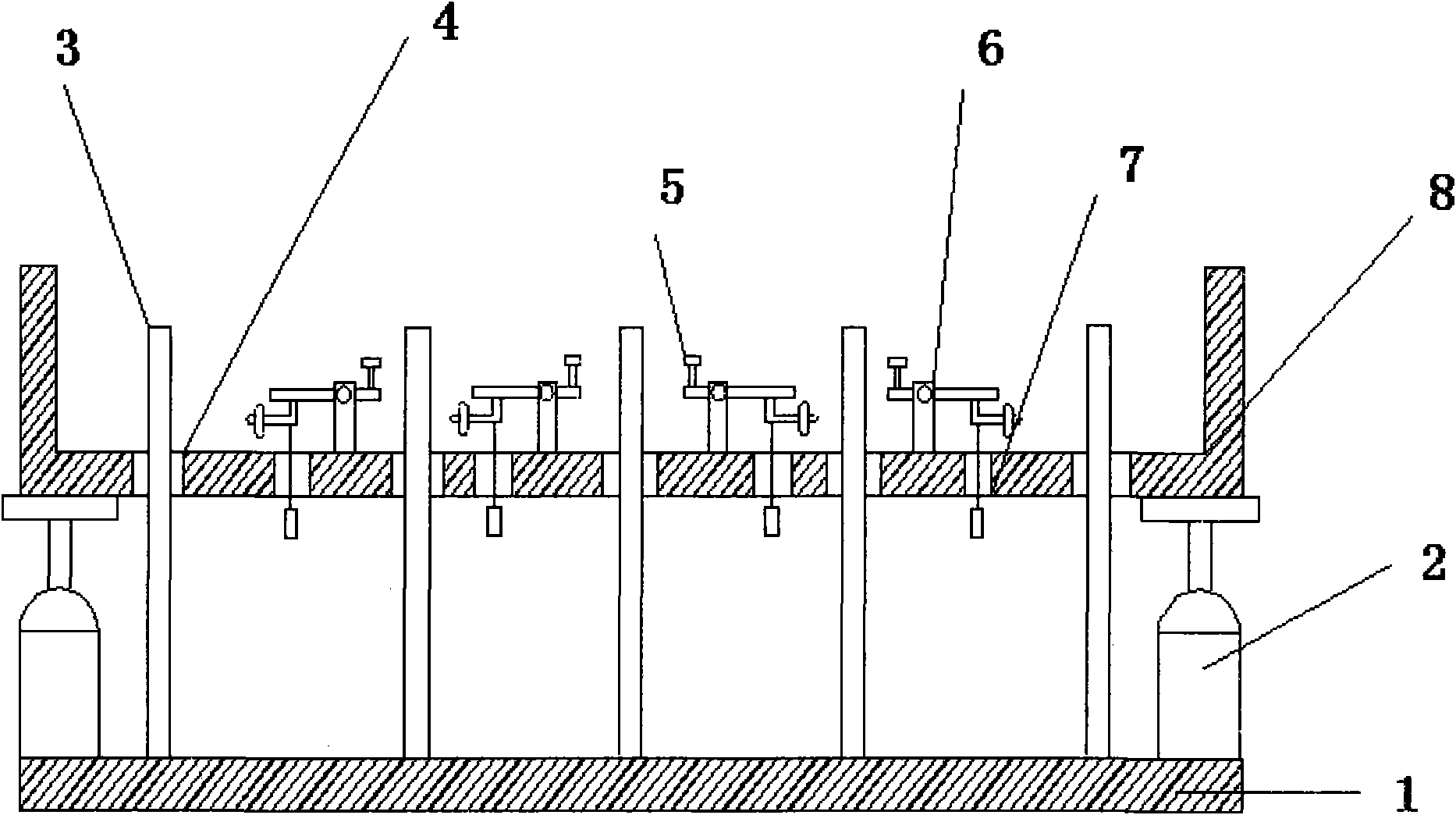
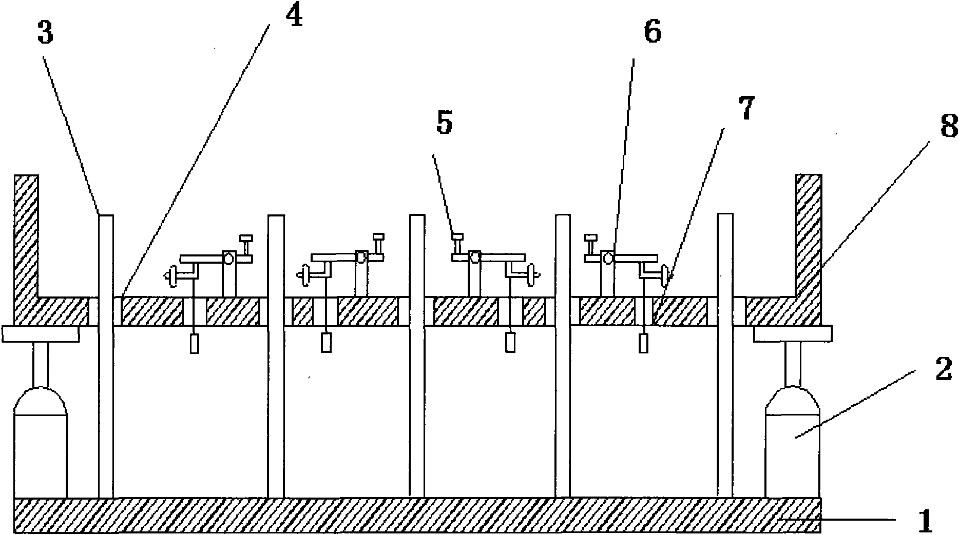
[0026] See attached figure 1 , which is a schematic structural cross-sectional view of a support system for processing large-aperture space optical mirrors provided in this embodiment. Depend on figure 1 It can be seen that two sets of support systems are used for the detection and processing of mirror workpieces. The rigid support rod 3 is installed on the processing support base plate 1 to form a processing support device. The device adopts rigid passive support to provide support force and bear the processing pressure; The detection support frame 8 and the floating active support mechanism 6 form a detection support device. The floating active support mechanism 6 is installed on the bottom plate of the detection support frame 8, and the three support points are fixed support points, which are evenly distributed on the same circumference. The support force is equal; there are rigid support rods passing through the hole 4 and the weight passing through the hole 7 on the bott...


PUM


Abstract

The invention discloses a supporting system for the machining of large-caliber space optical reflectors, which comprises a machining supporting device, a detection supporting device and a conversion mechanism (2), wherein the conversion mechanism is arranged on the upper surface of a machining supporting bottom plate (1), and supports the detection supporting device; the bottom plate of a detection supporting frame (8) is provided with a floating active supporting mechanism (6), a rigid supporting rod penetration hole (4) and a counter weight penetration hole (7); a rigid supporting rod (3) supports a work piece through the rigid supporting rod penetration hole in the machining of the reflector; and in detection, the conversion mechanism holds the detection supporting device up and the floating active supporting mechanism supports the work piece. By adopting a supporting way and a supporting structure which are mutually independent and adjustable, the supporting system can design schemes and accurately regulate supporting forces at each supporting point according to own characteristics of the reflectors to be machined, and also can regulate surface shape errors, caused by gravity deformation, of the reflectors to be acceptable for space usage, thereby greatly reducing ground detection errors.

Description

technical field [0001] The invention relates to a support technology for large-diameter optical mirrors in processing and detection, and belongs to the field of ultra-precision optical processing and detection. Background technique [0002] With the development of optical technology, the caliber of processed optical mirrors is increasing, and the support design and implementation of mirrors has become a very important technical link, because the deformation of the mirror itself under the action of gravity will directly affect the surface of the mirror. shape, and when such deformation reaches a certain level, it will have a great impact on detection and processing and directly affect the final mirror image quality. [0003] At present, the commonly used support methods for large-diameter optical mirrors mainly include single-row multi-row support and multi-point support. [0004] Single-row support refers to placing the circular optical mirror horizontally on a very narrow ...

Claims


Application Information

Patent Timeline
Patent Type & Authority Applications(China)
IPC IPC(8): G02B7/192G02B7/183G02B7/182
Inventor 黄启泰余景池张耀明
Owner SUZHOU UNIV
Why Eureka
Try Eureka