Check patentability & draft patents in minutes with Patsnap Eureka AI!

Synchronous rectification circuit

A synchronous rectification and circuit technology, which is applied to electrical components, AC power input conversion to DC power output, output power conversion devices, etc., can solve the problem of low conversion efficiency and achieve the effect of improving conversion efficiency

Active Publication Date: 2010-11-17
HUAWEI TECH CO LTD
View PDF0 Cites 1 Cited by
  • Summary
  • Abstract
  • Description
  • Claims
  • Application Information

AI Technical Summary

Problems solved by technology

[0004] The existing self-driven synchronous rectification circuit will enter the CCM (Continuous Current Mode) mode under light load, and the conversion efficiency is low

Method used


Image

  • Synchronous rectification circuit
  • Synchronous rectification circuit
  • Synchronous rectification circuit

Examples


Embodiment Construction

[0031] In order to facilitate the understanding of the embodiments of the present invention, several specific embodiments will be taken as examples for further explanation below in conjunction with the accompanying drawings, and each embodiment does not constitute a limitation to the embodiments of the present invention.

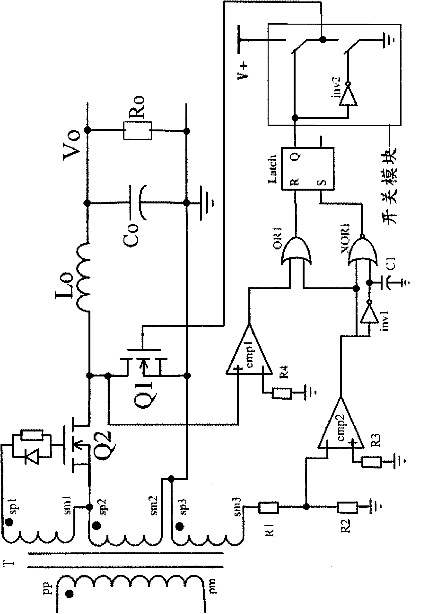
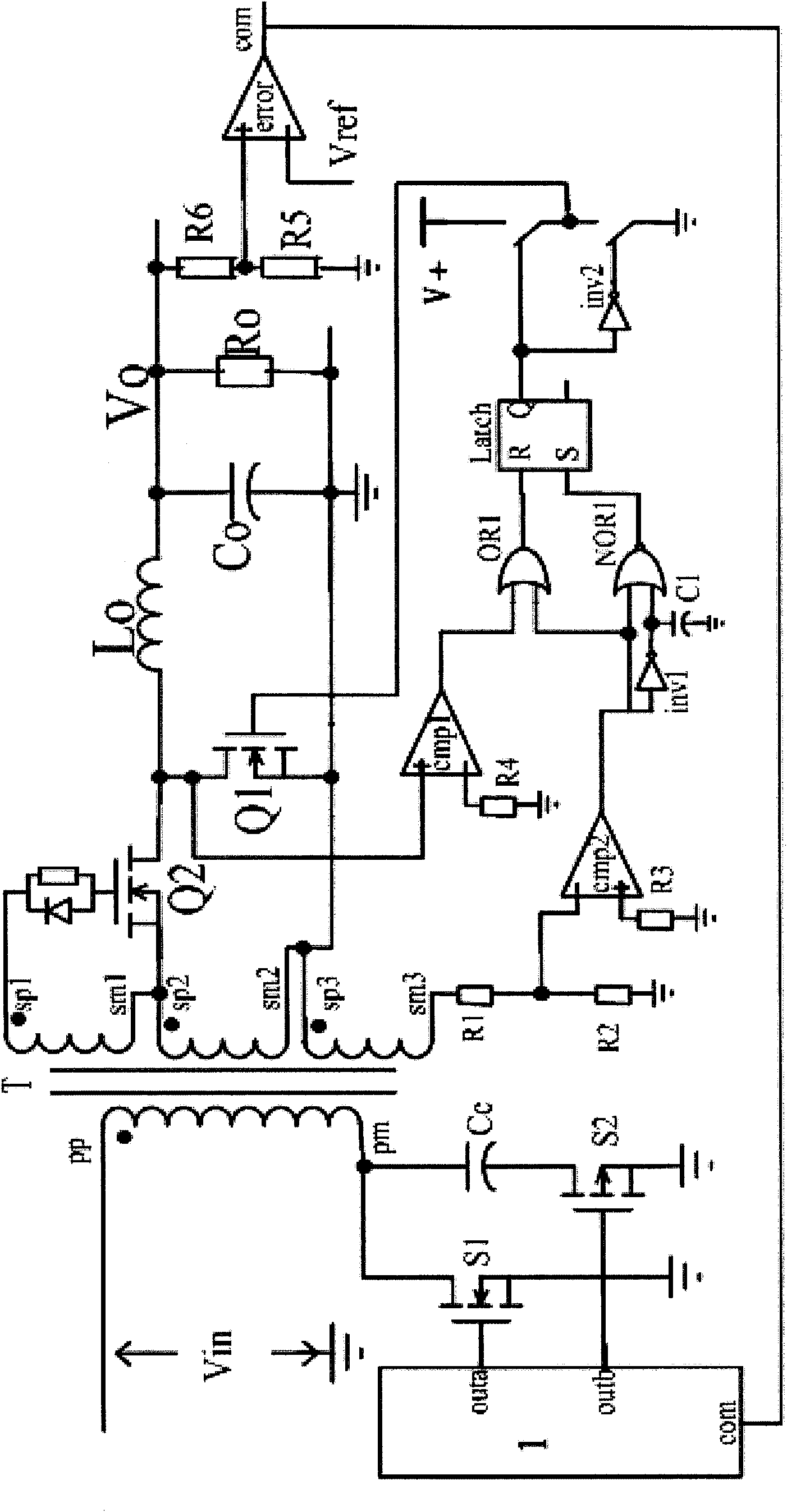
[0032] Such as figure 2 As shown, a synchronous rectification circuit, including:

[0033] A rectifier tube Q2, the gate of the rectifier tube Q2 is connected to the first terminal sp1 of the first secondary winding of the transformer, and the source of the rectifier tube Q2 is connected to the first terminal sp2 of the second secondary winding of the transformer, so The drain of the rectifier tube Q2 is connected to the drain of the freewheeling tube Q1;

[0034] a driving power supply connected to the gate of the freewheeling tube Q1, and used to provide a driving voltage for the freewheeling tube Q1;

[0035] A freewheeling tube Q1, the source of the f...


PUM


Abstract

The embodiment of the invention provides a synchronous rectification circuit, which comprises a rectifying tube, a driving power supply, a current-follow tube, a current-follow tube switch-off module, a current-follow tube switch-on module and a lightweight current-follow tube switch-off module, wherein the driving power supply is connected with a grid electrode of the current-follow tube and used for providing a driving voltage for the current-follow tube; the current-follow tube switch-off module is connected with the second end of a third secondary winding and the first end of a second secondary winding, and used for switching on the rectifying tube when the first end of the second secondary winding is in a high level and switching off the driving power supply when the second end of the third secondary winding is in a low level; the current-follow tube switch-on module is connected with the second end of the third secondary winding and a drain electrode of the current-follow tube, and used for switching off the rectifying tube when the first end of the second secondary winding is in a low level and switching on the driving power supply to provide the driving voltage for the current-follow tube when the drain electrode of the current-follow tube is in a low level and the second end of the third secondary winding is in a high level; and the lightweight current-follow tube switch-off module is connected with the drain electrode of the current-follow tube, and used for switching off the driving power supply when the drain electrode of the current-follow tube is converted into a high level from the low level.

Description

technical field [0001] The invention relates to the field of communication module power supplies, in particular to a synchronous rectification circuit. Background technique [0002] Existing self-driven synchronous rectification circuits, such as figure 1 shown. Its driving voltage adopts the secondary terminal voltage of the transformer. In the figure, Q2 is a rectifier tube, and Q1 is a freewheeling tube. The resistor connecting the two gates is to delay the turn-on time, and the diode is to speed up the turn-off time. [0003] In the process of realizing the present invention, the inventors found that the synchronous rectifier drive method in the prior art has at least the following problems: [0004] The existing self-driven synchronous rectification circuit will enter a CCM (Continuous Current Mode) mode under light load, and the conversion efficiency is low. Contents of the invention [0005] Embodiments of the present invention provide a synchronous rectificatio...

Claims


Application Information

Patent Timeline
IPC IPC(8): H02M7/217
Inventor 杨丹白亚东
Owner HUAWEI TECH CO LTD
Features
  • R&D
  • Intellectual Property
  • Life Sciences
  • Materials
  • Tech Scout
  • Unparalleled Data Quality
  • Higher Quality Content
  • 60% Fewer Hallucinations
Learn More