Method and device for controlling security means for a vehicle

A safety device and vehicle technology, applied in vehicle safety arrangement, pedestrian/occupant safety arrangement, vehicle components, etc., can solve problems such as insufficient consideration of torque, and achieve the effect of avoiding waiting time

Inactive Publication Date: 2010-11-17
ROBERT BOSCH GMBH
View PDF8 Cites 7 Cited by
  • Summary
  • Abstract
  • Description
  • Claims
  • Application Information

AI Technical Summary

Problems solved by technology

[0009] A disadvantage of the personal protection systems described in the prior art is that the torques acting during the collision are not sufficiently taken into account

Method used


Image

  • Method and device for controlling security means for a vehicle
  • Method and device for controlling security means for a vehicle
  • Method and device for controlling security means for a vehicle

Examples


Embodiment Construction

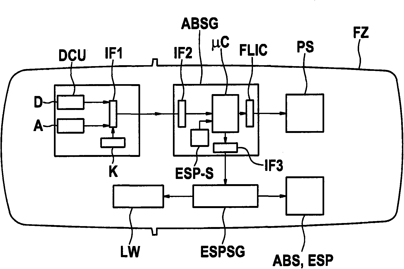
[0041] figure 1 A block circuit diagram of a device according to the invention with connected components is shown. The airbag control unit ABSG, as a device according to the invention, has an evaluation circuit in the form of a microcontroller μC, which evaluates the sensor signal and triggers the ignition circuit (Zündkreisschaltung) FLIC as a function of it in such a way that the ignition circuit depends on the sensor The signal triggers a personal protection device PS, such as an airbag or a seat belt pretensioner. In addition, the evaluation circuit μC can transmit a trigger signal via the interface IF3 to a further control device ESPSG, ie for the driving dynamics regulation, so that the driving dynamics regulation controls the steering angle LW as a function of the trigger signal or according to the specified The actuating signal described above actuates the braking system ABS or the driving dynamics control system ESP.

[0042] The sensor signals are provided on the o...


PUM


Abstract

The invention relates to a method and to a device for controlling security means for a vehicle. A sensor for producing at least one yam acceleration signal is provided. An evaluation circuit is used to scan the at least one yam acceleration signal at a scanning time of less than 10ms and for producing a control signal in accordance with the at least one scanned yam acceleration signal.

Description

technical field [0001] The invention relates to a method for triggering a vehicle safety device and a corresponding device. Background technique [0002] DE 101 49 112 A1 already has a method for forming a triggering decision for a restraint system, which relates in particular to the case of dirt roads. A dirt road is understood to be a situation in which a vehicle skids sideways after a skidding process and then sinks into a subsoil with a high coefficient of friction, for example unreinforced subsoil next to a roadway. The triggering decision is determined on the basis of driving dynamics data, wherein the sideslip angle is used as driving dynamics data in combination with the vehicle lateral speed and the vehicle tilting motion. The trigger decision is formed by a corresponding threshold value comparison. [0003] A method is known from WO-2005 / 030536 A1 for forming an activation decision for a restraint system, in particular during a rollover. In this case, the trigge...

Claims


Application Information

Patent Timeline
Patent Type & Authority Applications(China)
IPC IPC(8): B60R21/01B60W30/08
CPCB60W30/08B60R21/0132B60R2021/01259B60T8/17551B60R2021/0018B60T2201/024B60R2021/0119B60R2021/0006B60R2021/01327B60R2021/01068B60R2021/0004B60R21/01336B60R21/01338B60R21/0133
Inventor J·贝克尔T·利希A·德尔J·科拉特舍克M·希默
Owner ROBERT BOSCH GMBH
Why Eureka
Try Eureka