Friction stir welding method for stirring pin and shaft shoulder during differential speed rotation

A friction stir and welding method technology, applied in welding equipment, non-electric welding equipment, metal processing equipment and other directions, can solve the problems of huge energy consumption of equipment, strict clamping requirements, large forward resistance, etc., to improve production efficiency, clamping The effect of reduced requirements and faster welding speed

Inactive Publication Date: 2010-11-24
HARBIN INST OF TECH
View PDF5 Cites 13 Cited by
  • Summary
  • Abstract
  • Description
  • Claims
  • Application Information

AI Technical Summary

Problems solved by technology

[0004] The purpose of the present invention is to solve the problems of large downforce, large torque, large forward resistance, strict clamping requirements, large equipment and high energy consumption in conventional friction stir welding, and also to overcome the high-speed rot

Method used


Image

  • Friction stir welding method for stirring pin and shaft shoulder during differential speed rotation
  • Friction stir welding method for stirring pin and shaft shoulder during differential speed rotation
  • Friction stir welding method for stirring pin and shaft shoulder during differential speed rotation

Examples


specific Embodiment approach 1

[0014] Specific implementation mode one: as Figure 1~3 As shown, a friction stir welding method in which the stirring needle and the shaft shoulder rotate at a differential speed described in this embodiment is realized according to the following steps:

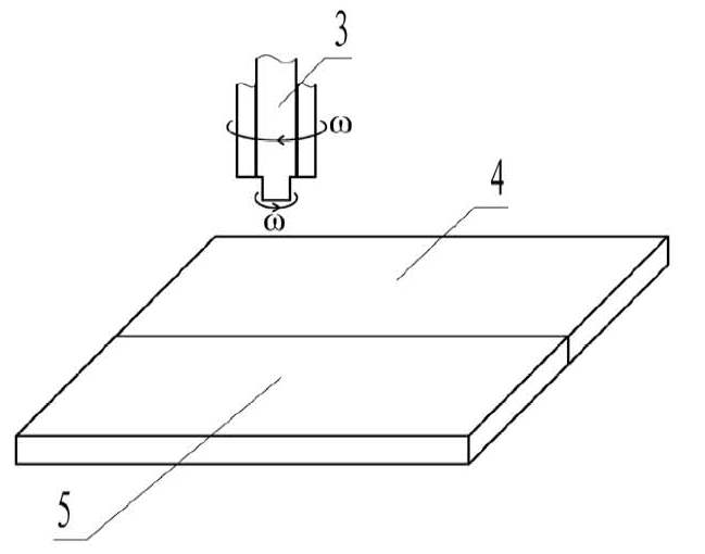
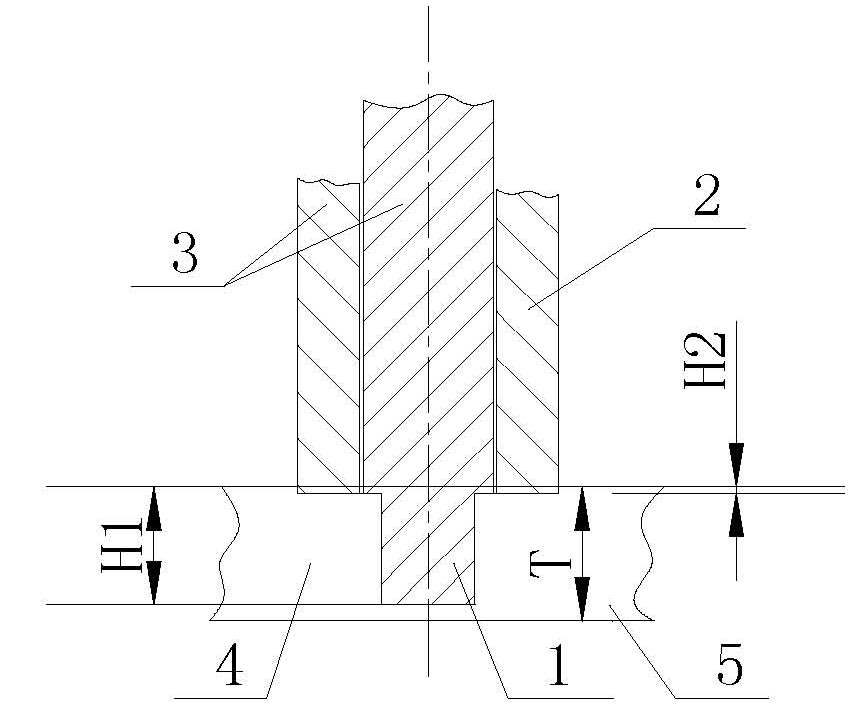
[0015] Step 1. Set the first workpiece 4 to be welded and the second workpiece 5 to be welded butt-connected and both are located on the same horizontal plane (that is, the first workpiece to be welded 4 and the second workpiece to be welded 5 are paired), and clamped on the On the workbench; the first workpiece to be welded 4 and the second workpiece to be welded 5 are plates;

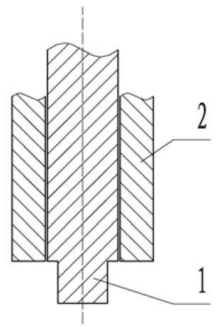
[0016] Step 2, the stirring needle 1 of the stirring head 3 is rotated at a speed of 3000 to 30000 rpm Into the part to be welded (that is, the butt surface of the first workpiece 4 to be welded and the second workpiece 5 to be welded); the rotation speed of the shoulder 2 of the stirring head 3 Lower than the rotation speed of Stirring Needle 1...

specific Embodiment approach 2

[0018] Specific embodiment two: In step two of this embodiment, the rotational speed of the shaft shoulder 2 100-800 rpm. The rotational speed of the shoulder 2 can be selected according to the specific conditions of the first workpiece 4 and the second workpiece 5 to be welded, so as to reduce the lowering and forward resistance of the stirring head 3 . Other steps are the same as in the first embodiment.

specific Embodiment approach 3

[0019] Specific embodiment three: In step two of this embodiment, the piercing speed of the stirring head 3 is 2-4 mm / min. The penetration speed of the stirring head 3 can be selected according to the specific conditions of the first workpiece 4 to be welded and the second workpiece 5 to be welded, so that the stirring head 3 can easily penetrate into the workpiece to be welded. Other steps are the same as those in Embodiment 1 or 2.


PUM


Abstract

The invention discloses a friction stir welding method for a stirring pin and a shaft shoulder during differential speed rotation, relates to the friction stir welding method and solves the problems of high downward pressure and high forward resistance and various problems caused by overcoming high speed rotation of the stirring pin and high speed rotation of the shaft shoulder in the same direction or non-rotation of the shaft shoulder existing in conventional friction stir welding. The method comprises the following steps of: inserting the stirring pin of a stirring head into a part to be welded at a rotation speed of between 3,000 and 30,000 rpm, wherein the rotation speed of the shaft shoulder of the stirring head is less than that of the stirring pin and the rotation direction of the stirring head is reverse to that of the stirring pin; the rotation speed of the shaft shoulder is 10 to 1,000 rpm; the insertion speed of the stirring head is 1 to 5 millimeter/minute; the depth of the stirring pin inserted into a workpiece is 0 to 0.5mm less than the thickness of the workpiece; and the depth of the shaft shoulder inserted into the workpiece is 0 to 0.5mm; and moving the stirring head along the horizontal direction of a butting surface of a first welded workpiece and a second welded workpiece at a speed of between 100 and 5,000 millimeter/minute. The heat required by the welding does not depend on the friction between the shaft shoulder and the welded material, so high downward pressure is not needed to ensure the friction of the shaft shoulder part to produce heat and the downward pressure is reduced.

Description

technical field [0001] The invention relates to a friction stir welding method, which belongs to the technical field of welding. Background technique [0002] Friction stir welding is a new type of solid-phase joining technology, which overcomes the problems of welding defects such as cracks and pores in the fusion welding method, and enables some materials that were difficult to weld in the past to achieve high-quality welding, and has become aluminum, magnesium and other materials in one fell swoop. The preferred welding method for its alloys. However, conventional friction stir welding has the following disadvantages: (1) More than 80% of the frictional heat generation comes from the friction between the shoulder and the material to be welded, and a large downforce is required to generate sufficient heat during the welding process; (2) The temperature of the material to be welded near the stirring head is low, and the torque required for the rotation of the stirring head...

Claims


Application Information

Patent Timeline
IPC IPC(8): B23K20/12B23K20/24
Inventor 刘会杰张超群李金全张会杰赵运强
Owner HARBIN INST OF TECH
Why Eureka
Try Eureka