
Computer interlocking system and operation method thereof

A technology of computer interlocking and interlocking machine, which is applied to interlocking devices between turnouts and signals, railway car body parts, railway signals and safety, etc., and can solve problems such as large system size, increased design cost, and complex system structure

Active Publication Date: 2010-11-24
上海亨钧科技股份有限公司
View PDF10 Cites 26 Cited by
  • Summary
  • Abstract
  • Description
  • Claims
  • Application Information

AI Technical Summary

Problems solved by technology

Although this kind of control device shows that the railway signal light control unit composed of safety relays is replaced by an electronic circuit, there are serious problems in the application process of this kind of control circuit, mainly because the above-mentioned fail-safe unit is composed of a dynamic circuit, and its function is The pulses output by the CPU processing units A and B are converted into a stable voltage for controlling the switch in the normally closed state. From this, it can be seen that only the CPU processing units A and B can achieve fault-oriented safety. In this way, this structure is similar to There is the same defect in the above-mentioned interlocking turnout execution unit circuit
[0008] Although a higher safety factor can be obtained through relays, on the one hand, the extensive use of relays will lead to complex structure and larger system volume, and on the other hand, it will greatly increase the design cost, because the station computer interlocking system The unit price of the relays used in the system is thousands of yuan. Therefore, how to ensure the high reliability of fault-oriented safety on the basis of using as few relays as possible has become an important task in the development of computer interlocking systems.

Method used


Image

  • Computer interlocking system and operation method thereof
  • Computer interlocking system and operation method thereof
  • Computer interlocking system and operation method thereof

Examples


Embodiment Construction

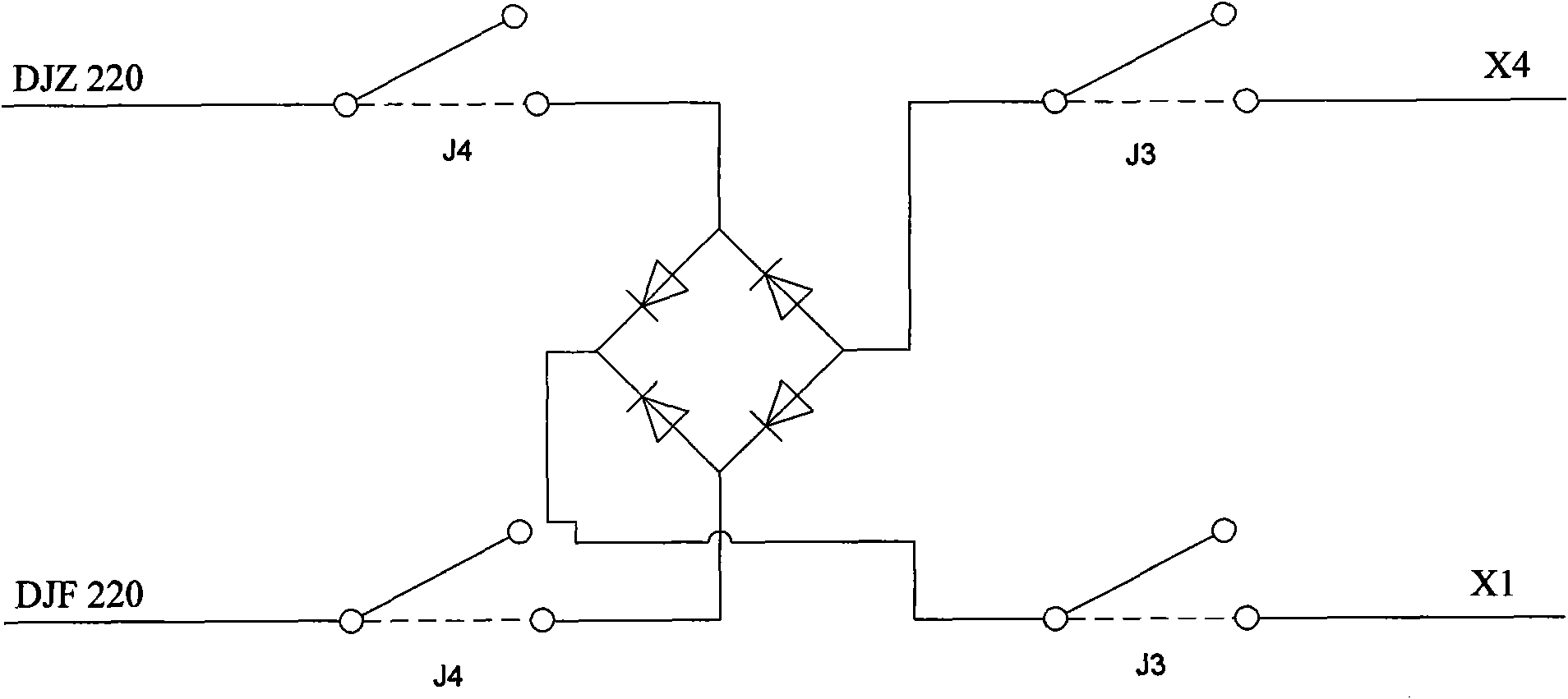
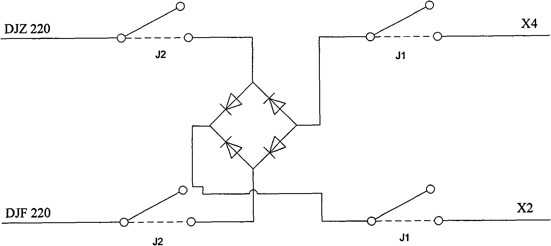
[0051] Such as figure 2 As shown, the computer interlocking system includes an interlocking machine, a communication gateway, and a turnout, a signal, a track, and a scattered execution unit; each of the turnout, a signal, a track, and a scattered execution unit is equipped with two controllers. The interlocking machine and the communication gateway of the computer interlocking system respectively realize the two-way communication between the interlocking machine and a controller of the turnout, signal, track and scattered execution unit through an interlocking machine bus A2 and an execution bus A1, The interlocking machine and the communication gateway realize two-way communication between the interlocking machine and another controller of the turnout, signal, track and scattered execution units through another interlocking machine bus B2 and another execution bus B1 respectively. The turnout, signal, track and scattered execution units are all provided with their own state...


PUM


Abstract

The invention discloses a computer interlocking system and an operation method thereof. The interlocking system comprises an interlocking machine, a communication gateway, a turnout execution unit, a signal execution unit and a track execution unit, wherein the turnout execution unit comprises a first action controller, a second action controller, a directional operation control ciruit, a reversed operation control circuit, a safety relay and a select switch, wherein the first action controller and the second action controller are used for controlling a group of switching tubes respectively arranged on the directional operation control circuit and the reversed operation control circuit, alternating current is input into the directional operation control circuit and the reversed operation control circuit and is controlled by the normally-open switch of the safety relay, the select switch is in communication connection with the first action controller, the second action controller and a signal collecting unit, and output of the first action controller, the second action controller and the select switch controls the safety relay by means of logical relation treatment. The invention uses the switching tubes to replace relays in the existing system, and adopts one safety relay and one select switch to ensure high reliability of the turnout execution unit, thereby greatly reducing cost of the whole system on the premise of ensuring the high reliability.

Description

technical field [0001] The invention relates to a computer interlocking system for a station and a working method thereof, in particular to an improvement of a turnout execution unit used in the computer interlocking system for controlling a switch machine to drive a turnout for fixed operation and reverse operation positioning. Background technique [0002] The current computer interlocking system generally includes an interlocking machine and a communication gateway, as well as a turnout execution unit, a signal execution unit, a track execution unit, and a scattered execution unit controlled by the interlocking machine, wherein the turnout execution unit is responsible for controlling the switch machine Drive the turnout for fixed operation and anti-operation positioning; the signal execution unit is used to control the display of the shunting signal machine and the signal machine entering and leaving the station, that is, to control the display of various signal lights; t...

Claims


Application Information

Patent Timeline
IPC IPC(8): B61L19/06G05B19/04
Inventor 王锁平段磊项银芬陈真刘宇驰赵丽宏何建宏韩冬李宪国王建强
Owner 上海亨钧科技股份有限公司
Learn More