Multi-stage heat exchanger

A heat exchanger and condenser technology, applied in the direction of evaporator/condenser, lighting and heating equipment, refrigeration components, etc., can solve the problem of reduced heat exchange efficiency of heat exchanger, unsatisfactory power consumption index, and failure to achieve cooling purposes and other problems, to achieve the effect of improving heat exchange efficiency, saving energy and improving utilization rate

Inactive Publication Date: 2010-11-24
南京平欧空调设备有限公司
View PDF0 Cites 8 Cited by
  • Summary
  • Abstract
  • Description
  • Claims
  • Application Information

AI Technical Summary

Problems solved by technology

[0002] Before the present invention, the cooling water circuit design of the existing heat exchanger is a single circuit design, and its disadvantage is that the water temperature of the cooling water continues to increase as the distance travels, and as the temperature of the cooling water increases, the temperature of the heat exchanger The heat transfer efficiency will gradually decrease, and the cooling purpose cannot be achieved.
In addition, the existing design is generally limited by water flow and water pressure drop, so it is necessary to use thicker diameter heat exchange tubes, such as heat exchangers in the form of flooded heat exchange, which increases the manufacturing cost; Due to the low heat exchange efficiency of the heater, the power consumption index is not ideal, and at the same time, the material input is greatly increased, wasting precious resources

Method used


Image

  • Multi-stage heat exchanger
  • Multi-stage heat exchanger
  • Multi-stage heat exchanger

Examples


Embodiment Construction

[0014] Structure of the present invention:

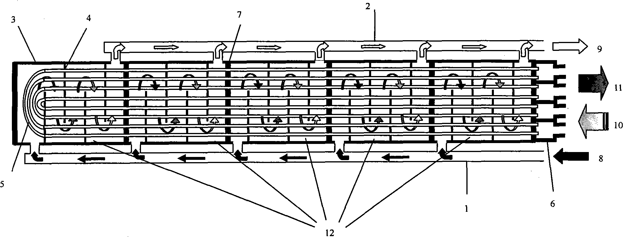
[0015] Such as figure 1 Shown:

[0016] The liquid inlet header 1 and the liquid outlet header 2 are arranged on both sides of the cylinder 3, or they can be arranged on the same side; the starting end of the liquid inlet header 1 is the liquid inlet 8, and the end of the liquid outlet header 2 is the liquid outlet 9. The partition plate 7 divides the cylinder body 3 into a plurality of cavities 12, in this example, five cavities 12; the head 6 divides the open end of the tube bundle 5 into multiple refrigerant inlets and outlets, in this example, 5 pairs The refrigerant inlet 10, the refrigerant outlet 11, together with the head 6 and the tube bundle 5 form 5 independent refrigerant inlet and outlet systems.

[0017] The liquid inlet 8 and the liquid outlet 9 of the liquid inlet header 1 and the liquid outlet header 2 can be in any orientation of the liquid inlet header 1 and the liquid outlet header 2 . Such as at both ends, at...


PUM


Abstract

The invention relates to a multi-stage heat exchanger. A liquid-collecting inlet tube and a liquid-collecting outlet tube are arranged on two sides of a cylinder, the beginning end of the liquid-collecting inlet tube is a liquid inlet while the tail end of the liquid-collecting outlet tube is a liquid outlet, and a baffle plate is connected in the middle of the liquid-collecting inlet tube and the liquid-collecting outlet tube. The multi-stage heat exchanger is mainly technically characterized in that a separator plate divides the cylinder into a plurality of cavities, and the opening end of a tube bundle is divided into a plurality of pairs of refrigerant inlets and refrigerant outlets by a seal head to form a separate refrigerant in-out system. The invention solves the defects of continuous improvement of single circuit cooling water along with the traveling of the course, gradual reduction of heat exchange efficiency, high manufacture cost, low heat exchange efficiency of a dry-steaming type heat exchanger, high power consumption, large input of materials and the like. The invention has the advantages of high heat exchange efficiency, energy-saving, reduction of product cost and operation cost as well as larger temperature difference of refrigerant temperature, thereby a favorable heat exchange condition is formed.

Description

technical field [0001] The invention relates to a high-efficiency heat exchanger, in particular to a multi-stage heat exchanger. Background technique [0002] Before the present invention, the cooling water circuit design of the existing heat exchanger is a single circuit design, and its disadvantage is that the water temperature of the cooling water increases continuously with the distance, and as the temperature of the cooling water increases, the temperature of the heat exchanger The heat exchange efficiency is gradually reduced, and the cooling purpose cannot be achieved. In addition, the existing design is generally limited by water flow and water pressure drop, so it is necessary to use thicker diameter heat exchange tubes, such as heat exchangers in the form of flooded heat exchange, which increases the manufacturing cost; Due to the low heat exchange efficiency of the heater, the power consumption index is not ideal, and at the same time, the material input is great...

Claims


Application Information

Patent Timeline
Patent Type & Authority Applications(China)
IPC IPC(8): F25B39/00
Inventor 庄迪君
Owner 南京平欧空调设备有限公司
Why Eureka
Try Eureka