Magnetic material antenna and antenna device
A technology of magnetic body and magnetic body core, which is applied in the direction of antenna, loop antenna with ferromagnetic material core, antenna parts, etc., which can solve the problems of short distance, small number of coil windings, and decreased antenna sensitivity
- Summary
- Abstract
- Description
- Claims
- Application Information
AI Technical Summary
Problems solved by technology
Method used
Image

Examples
no. 1 Embodiment approach
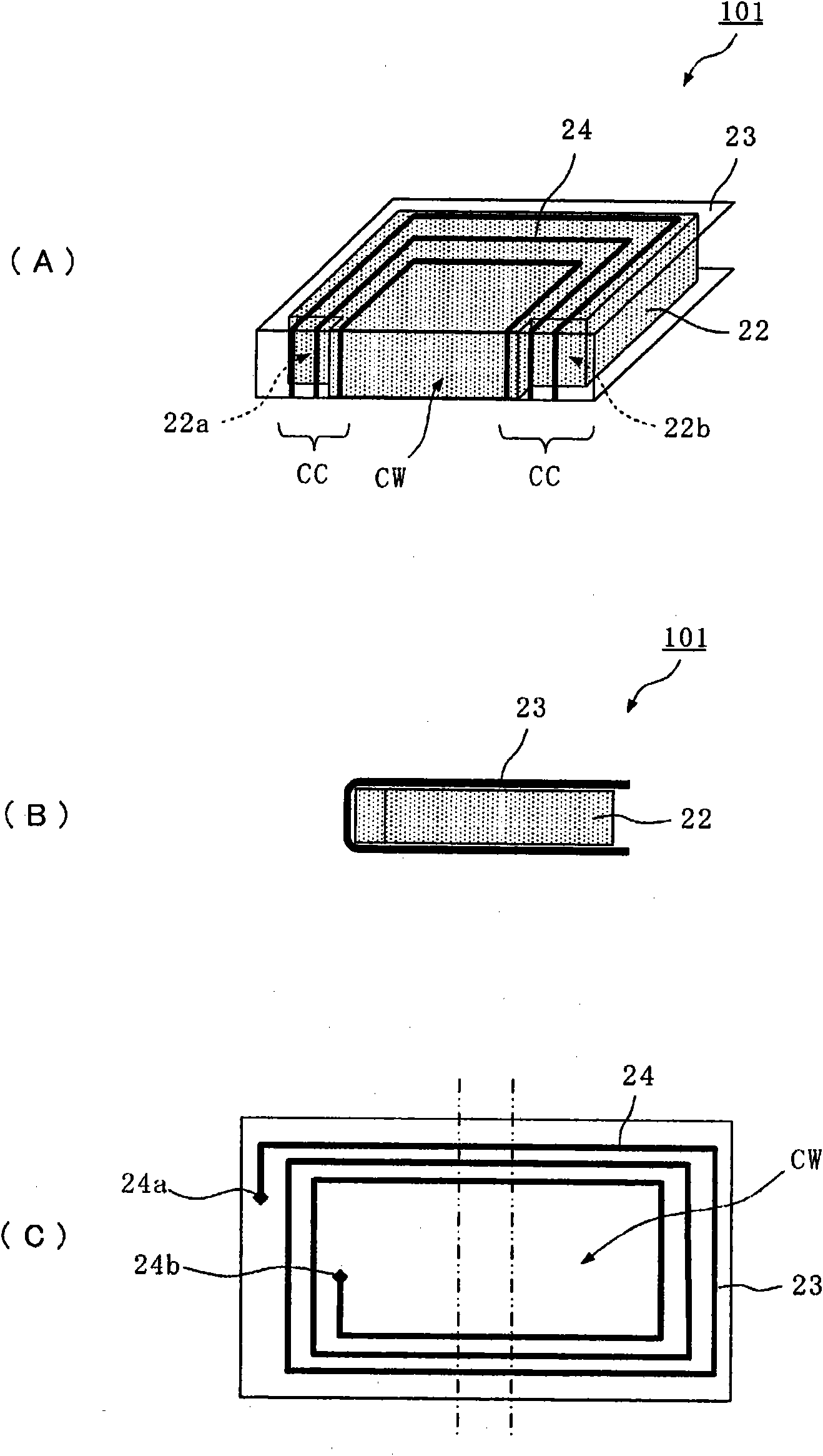
[0069] figure 2 It is a figure which shows the structure of the magnetic substance antenna in 1st Embodiment, (A) is a perspective view of the magnetic substance antenna 101, (B) is its side view, (C) is the development of the flexible substrate used for this magnetic substance antenna floor plan.
[0070] Such as figure 2 As shown in (A) and (B), the magnetic antenna 101 has the flexible substrate 23 on which the coil conductor 24 is formed, and the magnetic core 22 . A spiral coil conductor (electrode) 24 is formed on the flexible substrate 23 , and a winding center portion of the coil conductor 24 is formed as a conductor opening CW. That is, the helical coil conductor 24 is formed so as to surround the conductor opening CW.
[0071] figure 2 The two-dot chain line in (C) indicates the bending position of the flexible substrate 23 . Such as figure 2 (A) As shown in (B), the flexible substrate 23 is bent along the two-dot chain line with respect to the magnetic cor...
no. 2 Embodiment approach
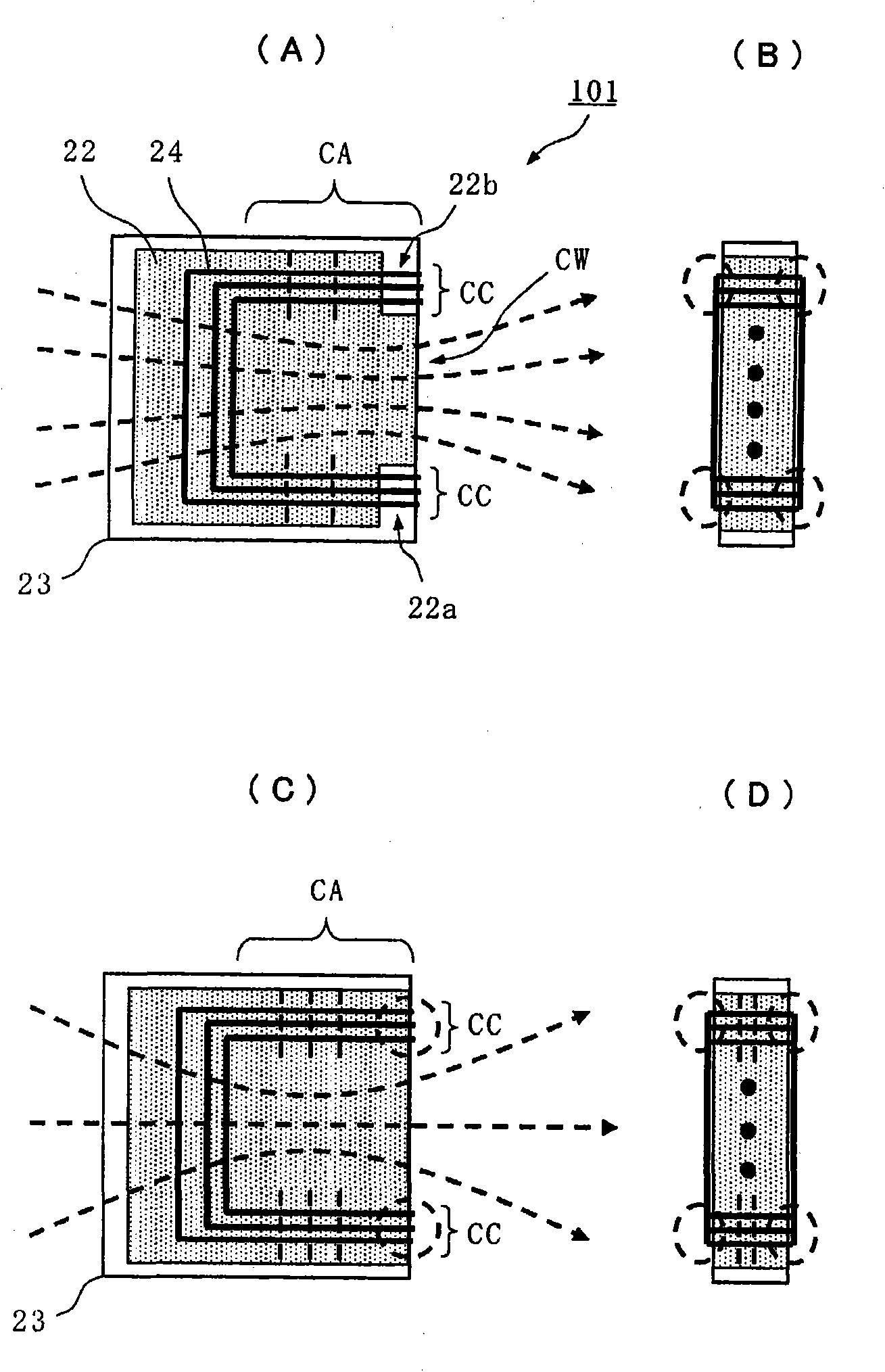
[0083] Figure 4 It is a figure which shows the structure of the magnetic substance antenna in 2nd Embodiment, (A) is its perspective view, (B) is its three-sided view. The magnetic antenna 102 is as Figure 4 As shown in (A), the end surface of the magnetic core 22 is arranged in a state facing the curved portion of the flexible substrate 23, and the coil conductor portion CC facing the curved portion of the flexible substrate 23 is located among the end surfaces of the magnetic core 22. The tapered notch-shaped portions 22c and 22d are formed toward the conductor opening CW.
[0084] In this way, by making the notch-shaped portion face the conductor opening CW, and having a tapered shape with a tapered tip, the magnetic flux is concentrated at the tapered portion and concentrated in the opening of the coil conductor, so that the magnetic flux is easy to pass through, that is, the magnetic flux is collected. As the efficiency increases, the sensitivity of the antenna furthe...
no. 3 Embodiment approach
[0086] Figure 5 It is a figure which shows the structure of the magnetic substance antenna in 3rd Embodiment, (A) is this magnetic substance antenna 103 perspective view, (B) is this flexible board|substrate 23 used for this magnetic substance antenna 103 development plan view.
[0087] This magnetic antenna 103 has a flexible substrate 23 forming a coil conductor 23 and a magnetic core 22. The flexible substrate 23 forms a spiral coil conductor 24 with the winding center portion as a conductor opening CW, and is positioned at the center of the conductor opening CW. A hole 23W is formed.
[0088] On the other hand, the magnetic core 22 is arranged in a state where the protruding portion 22 e passes through the hole 23W formed in the bent portion of the flexible substrate 23 . In addition, notch-shaped parts 22 a and 22 b separated from the coil conductor part CC are formed in the part of the coil conductor part CC facing the bent part of the flexible substrate 23 .
[0089]...
PUM
 Abstract
Description
Claims
Application Information
 - R&D
- Intellectual Property
- Life Sciences
- Materials
- Tech Scout
- Unparalleled Data Quality
- Higher Quality Content
- 60% Fewer Hallucinations
Browse by: Latest US Patents, China's latest patents, Technical Efficacy Thesaurus, Application Domain, Technology Topic, Popular Technical Reports.
© 2025 PatSnap. All rights reserved.Legal|Privacy policy|Modern Slavery Act Transparency Statement|Sitemap|About US| Contact US: help@patsnap.com