Workpiece turnover unit, vacuum film-forming device and workpiece assembly unit

A technology for assembling units and workpieces, applied in vacuum evaporation plating, metal material coating technology, ion implantation plating, etc., can solve problems such as workpiece warpage, increased burden of space cost, waste, etc.

Inactive Publication Date: 2010-12-01
FUJI PHOTO OPTICAL CO LTD
View PDF5 Cites 8 Cited by
  • Summary
  • Abstract
  • Description
  • Claims
  • Application Information

AI Technical Summary

Problems solved by technology

[0005] However, although a film can be formed on the front and back of the workpiece in a vacuum, the flip is only once, and the film can be formed once on the front and back, so for multi-layer coatings such as the above-mentioned multiple film-forming substances, Each layer needs to open the cavity to reset the film-forming posture
Also, to open the chamber, the vacuum state must be released, and the internal temperature is also lowered from high temperature (for example, 100 to 400°C) to close to room temperature, so after resetting the workpiece, it must be set to high temperature and vacuum again, which takes a long time
[0006] In addition, when a plurality of different film-forming substances are formed into a film, the temperature of the film-forming substance (for example, forming a film at 400°C and then forming a film at 100°C, etc.) is sometimes different. In the method of continuous multi-layer film formation on the other side after filming, the stage of film formation on one side will cause warpage on the workpiece
Especially when the workpiece is a thin glass plate, it sometimes causes large warping and is not durable
[0007] In addition, the device described in Patent Document 1 must have a driving mechanism such as a motor in order to turn the workpiece inside the cavity. Even if the conventional device is modified, a large-scale change is required, and a large burden will be added in terms of space and cost.

Method used


Image

  • Workpiece turnover unit, vacuum film-forming device and workpiece assembly unit
  • Workpiece turnover unit, vacuum film-forming device and workpiece assembly unit
  • Workpiece turnover unit, vacuum film-forming device and workpiece assembly unit

Examples


Embodiment Construction

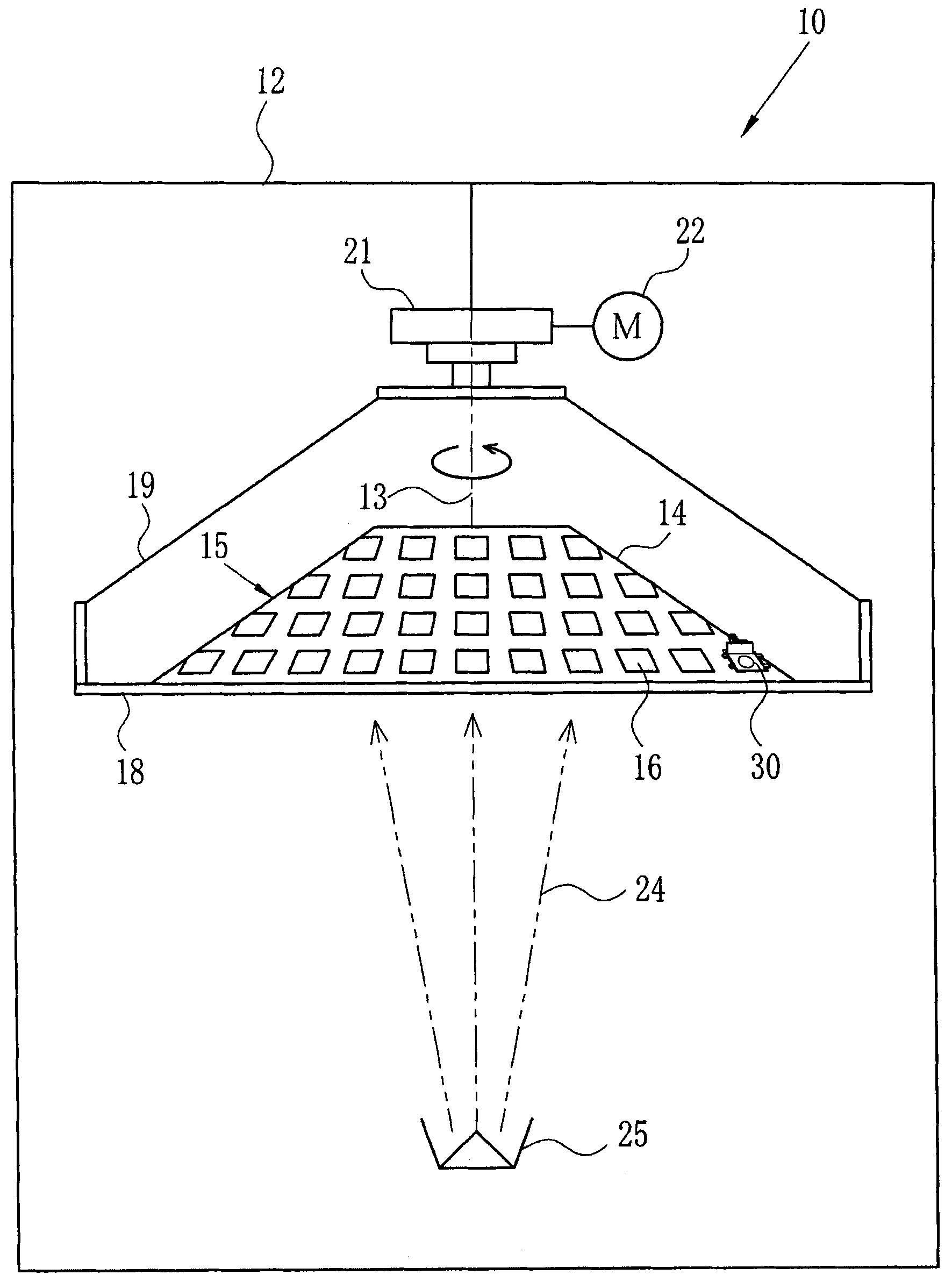
[0074] Such as figure 1 As shown, in the vacuum film forming apparatus 10, a dome (work holding plate) 15 having an umbrella-shaped inclined surface 14 that rotates around the axis of a vertical axis 13 is provided in a chamber (vacuum chamber) 12 whose interior is evacuated. A plurality of fitting holes (fitting portions) 16 for fitting the workpiece inverting unit 30 of the present invention are formed along the inclination (for example, 35°) of the inclined surface 14 . The dome 15 is fixed to a mounting ring 18 and is rotatably suspended from the ceiling of the chamber 12 by three support arms 19 . The three support arms 19 can be rapidly accelerated and decelerated while being rotated at a constant speed by a reduction gear unit (speed change mechanism) 21 and a motor 22 . The reduction gear unit 21 has a braking device (not shown). A film-forming substance generating source 25 for scattering a film-forming substance 24 is arranged at a lower position of the dome 15 . ...


PUM


Abstract

The present invention provides a workpiece turnover unit, a vacuum film-forming device and a workpiece assembly unit, wherein the workpiece turnover unit is capable of keeping a cavity of the vacuum film-forming device to be vacuum so as to film by turns on two faces of the workpiece. The vacuum film-forming device is capable of forming film on two faces of the workpiece continuously and directly that the cavity is of a vacuum state. A workpiece assembly unit (20) is arranged on a plurality of workpiece assembly parts (18) which are formed on a dome sloped surface in the cavity of the vacuum film-forming device. The workpiece assembly unit (20) includes a clamp support frame (25) for rotating-freely supporting a workpiece clamp (22) fixed with a glass plate (21) by a pair of rotating shafts, and a ball guiding frame (50) having a locking component (60) for locking the clamp support frame (25) from rotating. The ball guiding frame (50) is provided with a ball (58) held at a loading position through a rib (56). If a rotating speed of the dome is increased, the ball (58) may collide with a ball collision part (62) of the locking component (60) across the rib (56) by a centrifugal force, here, a locking claw (63) moves from a locking position of the workpiece clamp (22) and the workpiece clamp (22) is turned over.

Description

technical field [0001] The present invention relates to a workpiece reversing unit and a workpiece assembling unit in a vacuum film forming device for forming a film-forming substance on the front and back of a circular, square or other plate-shaped object to be filmed (workpiece). Background technique [0002] In a general vacuum film forming device, a workpiece holding disk such as a rotating dome in a substantially umbrella shape or a rotating drum in a polygonal cylindrical shape that rotates around a rotating shaft in a chamber that is vacuumed by a vacuum pump is provided, so that The film-forming substance emitted by the film-forming substance generating source in the cavity is evenly attached to the surface of the workpiece such as a glass plate. When a plurality of sources of film-forming substances are provided, different film-forming substances are sequentially deposited on the workpiece through a shielding plate or the like to form a film deposited on the workpie...

Claims


Application Information

Patent Timeline
Patent Type & Authority Applications(China)
IPC IPC(8): C23C14/56C23C14/24
Inventor 仓桥肇
Owner FUJI PHOTO OPTICAL CO LTD
Why Eureka
Try Eureka