Delay parameter computation method for multi-channel scanning and device thereof

A technology of delay parameters and calculation devices, which is applied in measurement devices, medical science, and re-radiation of sound waves, etc., and can solve problems such as difficulty in implementation, loss of precision, and complexity

Inactive Publication Date: 2010-12-01
SHENZHEN LANDWIND IND
View PDF5 Cites 11 Cited by
  • Summary
  • Abstract
  • Description
  • Claims
  • Application Information

AI Technical Summary

Problems solved by technology

[0003] Due to different types of probes, such as linear array, convex array, and phased array; different scanning methods, such as non-deflected scanning, deflected scanning, extended imaging (T-type) scanning, phased array scanning, and spatial compounding; different scanning densities , such as high, medium and low density scanning, the delay calculation method is more complicated
The traditional method is to download the delay parameters to the hardware memory, and take these parameters out of the memory during scanning to control the focus. On the one hand, it is necessary to update the memory area parameters when switching between different probes and scanning methods, which brings switching Transient; on the other hand, due to the large amount of data, especially the receiving scan in the case of T-scan, phased array scan, space composite, etc., the original dela

Method used


Image

  • Delay parameter computation method for multi-channel scanning and device thereof
  • Delay parameter computation method for multi-channel scanning and device thereof
  • Delay parameter computation method for multi-channel scanning and device thereof

Examples


Embodiment Construction

[0049] Below according to accompanying drawing and embodiment the present invention will be described in further detail:

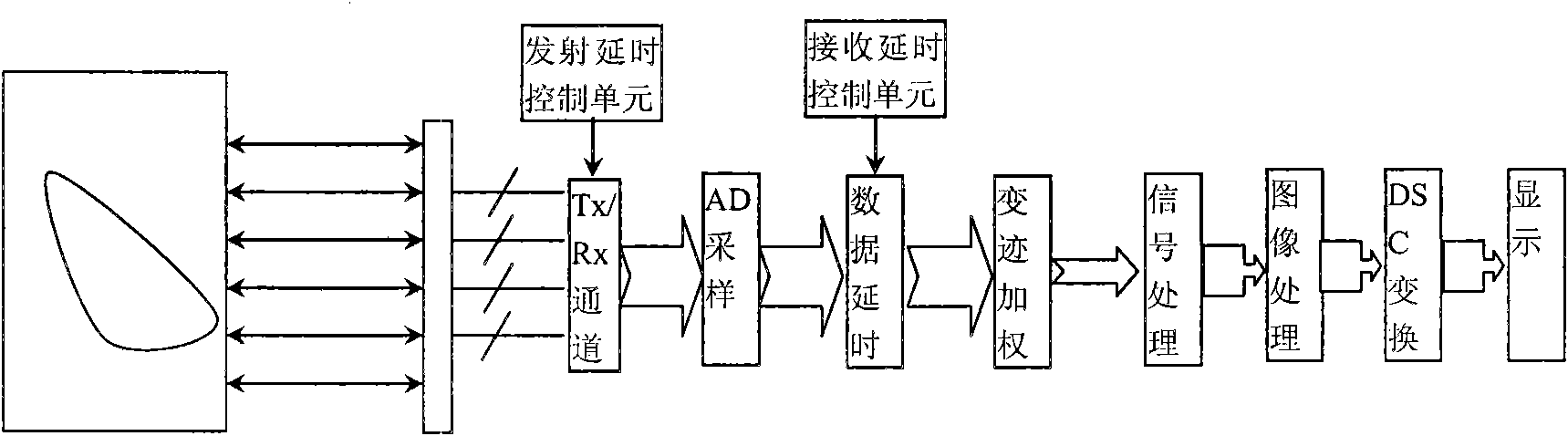
[0050] This embodiment provides a delay parameter calculation method, which unifies the delay calculation formulas of the three types of probes: linear array, convex array and phased array, and this calculation formula is applicable to both non-deflection scanning and deflection scanning. Scanning; scanning lines of different densities can also be calculated only by changing variables such as scanning line position, focus, etc.

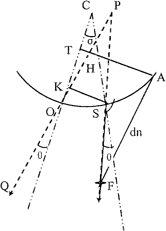
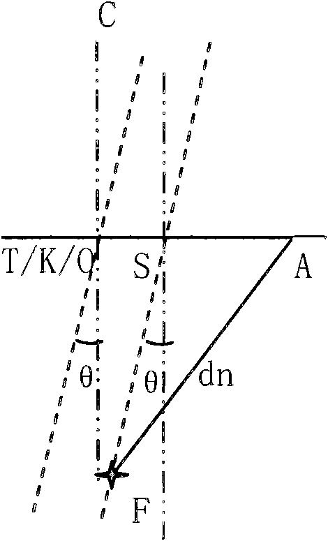
[0051] As wrong! Reference source not found. , figure 2 , C is the center of the convex array, O is the coordinate reference point, OC is the normal of the probe passing through O, A is the position of a certain array element, SF is the scan line, where S is the starting point of the scan line, F is the focus point, θ is the angle between the scanning line SF and the normal line of the probe passing through point S, that is, t...


PUM


Abstract

The invention provides a delay parameter computation method for a multi-channel scanning, which unifies delay computational formulas of three probes such as a linear array, a convex array and a phased array, and the formulas are applicable to non-deflection scanning and deflection scanning; and scanning lines with different densities can be calculated only by changing location variables of the scanning lines. In the invention, only an array element position, a scanning starting point position and relative focus parameters need to be stored, thus having small quantity of stored data; real-timecomputation can realize accurate delay without a large quantity of the stored data; delay in various situations for the probes, the density and deflection is calculated using a unified circuit to greatly simplify a circuit structure; and delay of each scanning line is independently controlled to conveniently realize arbitrary density scanning, for if no integral multiple relationship exists between spacing among the scanning lines and spacing among array elements of the probes, different scanning lines have different delay data. In the invention, the scanning lines are independently controlled, thus achieving arbitrary density scanning.

Description

technical field [0001] The present invention provides a method and device for real-time and precise control of multi-channel scanning delay parameters of an ultrasonic system, realizes accurate focusing of ultrasonic transmitting scans and receiving scans, improves the consistency of ultrasonic waves in each channel, and thereby improves the quality of ultrasonic imaging. Background technique [0002] In order to achieve accurate focusing during the transmission and scanning of the ultrasound system, each array element has a different sequence of transmission and reception according to the relative position of the space relative to the focal point. In the ultrasonic diagnostic system, whether it is B-type, C-type or D-type imaging, scanning focus is required to superimpose the transmission signals or echo signals of each channel in the same phase, improve the signal-to-noise ratio to increase the dynamic range of the signal, and The spatial resolution of the imaging is great...

Claims


Application Information

Patent Timeline
IPC IPC(8): G01S7/52G01S15/89A61B8/00
Inventor 张羽
Owner SHENZHEN LANDWIND IND
Why Eureka
Try Eureka