Reverse image device with ranging function

A technology of reversing image and function, applied in the field of reversing image device, can solve the problem of high cost and achieve the effect of avoiding misjudgment

Inactive Publication Date: 2010-12-01
H P B OPTOELECTRONICS
View PDF0 Cites 11 Cited by
  • Summary
  • Abstract
  • Description
  • Claims
  • Application Information

AI Technical Summary

Problems solved by technology

[0005] The purpose of the present invention is to solve the technical problem that the existing revers...

Method used


Image

  • Reverse image device with ranging function
  • Reverse image device with ranging function
  • Reverse image device with ranging function

Examples


Embodiment Construction

[0029] Regarding the technology, means and effects used in the present invention, a preferred embodiment is given and described in detail below with drawings, which are for illustration purposes only, and are not limited by this structure in the patent application.

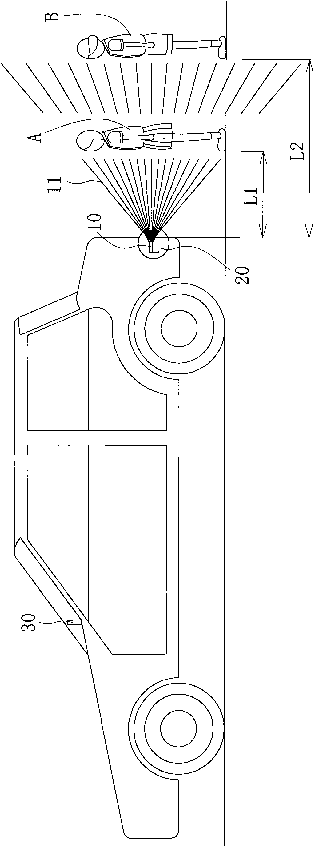
[0030] refer to figure 1 , is a schematic diagram of the use of the distance measuring function of the present invention. The present invention includes a light source 10, a lens group 20 and a display 30 to measure the images of the first object A and the second object B to be measured and the distance from the vehicle. distance, where:

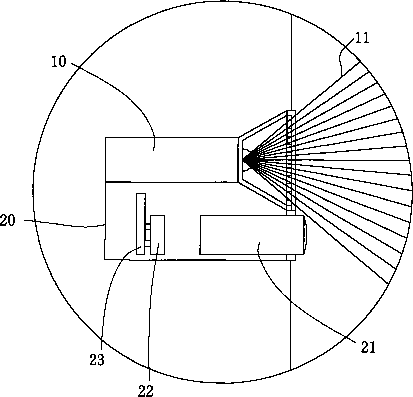
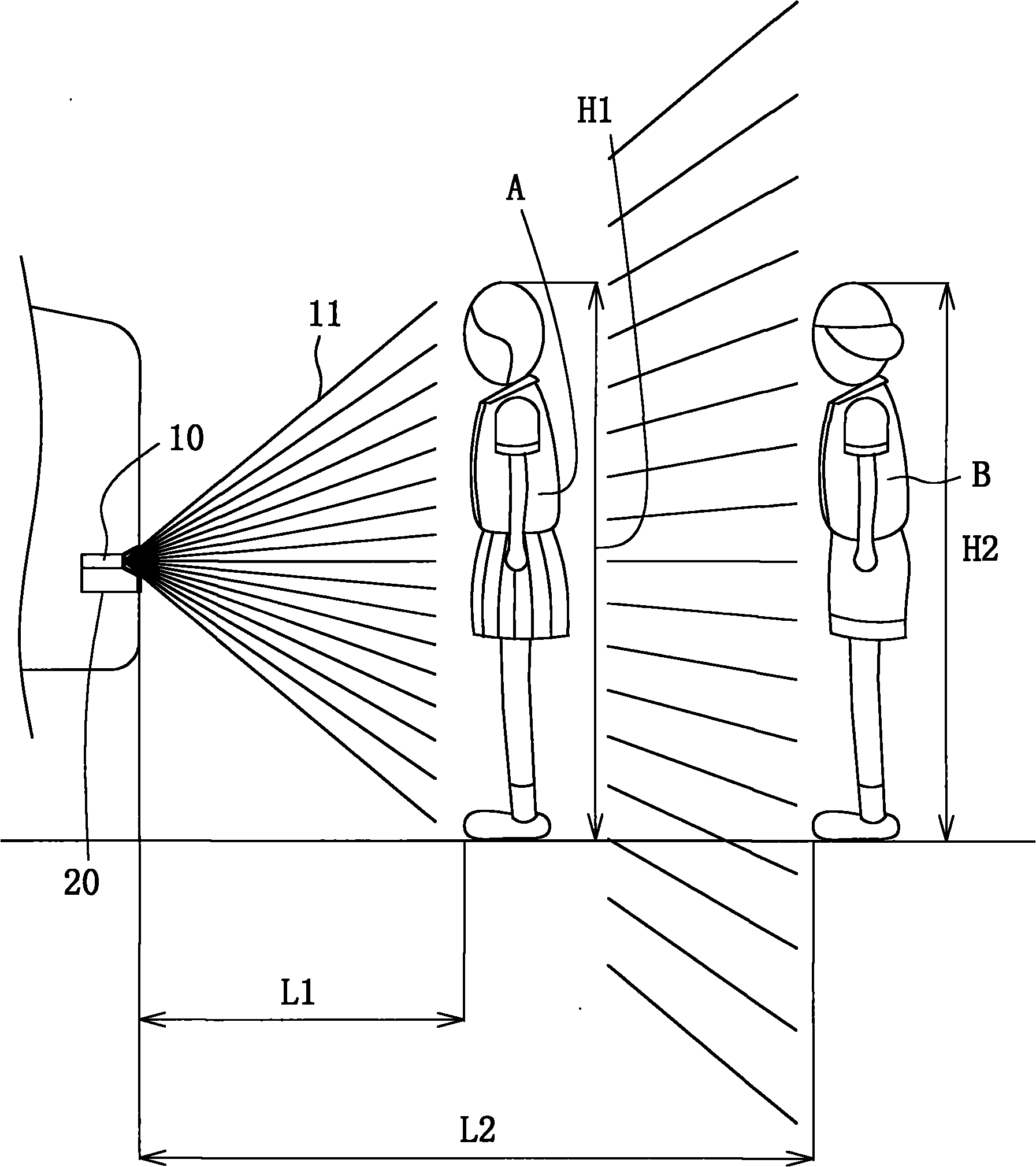
[0031] refer to Figure 2 to Figure 5 , the light source 10 is installed at the rear of the car, the light source 10 can project a light 11, the light 11 can be projected on the objects A and B at the rear of the car, and appear on the objects A and B A pattern 12, the pattern 12 is a regularly arranged mesh grid, and the light 11 is invisible light, so it will not affect the...


PUM


Abstract

A reverse image device with a ranging function is composed of a luminous source, a lens group and a display, wherein the luminous source is arranged at the tail of an automobile and can project a ray which can generate a pattern on an object to be measured; the lens group is arranged at the tail of the automobile and is internally provided with a lens, a photo-sensitive component and a circuit board, the lens collects images at the rear part of the automobile to be projected on the photo-sensitive component, and the circuit board calculates the off-car distance between the object to be measured and the tail of the automobile based on the pattern compactness read by the photo-sensitive component; and the display is arranged in the automobile for a driver to view and is electrically connected with the lens group so as to enable the display to display the off-car distance between the image of the object to be measured and the object to be measured. By pattern compactness projected by the luminous source, the off-car distance of the object to be measured is calculated so as to avoid the driver from judging the off-car distance of the object to be measured by mistake; and the ray is invisible light, thus having no influence on coming vehicles or pedestrians at the back.

Description

technical field [0001] The present invention mainly discloses a reversing image device with a distance measuring function, especially a reversing image device that uses light to project on an object to be measured to measure the distance from the vehicle. Background technique [0002] refer to Figure 9 to Figure 11 , is a schematic diagram and display screen of a conventional reversing image device, which has a lens 101 and a display 102, and there are a first object to be tested a and a second object to be tested b at the rear of the car, wherein the first object to be tested a and the second object to be tested The height and size of the two test objects b are about the same. When the lens 101 collects the first test object a and the second test object b respectively, on the screen of the display 102, the visual distance from the vehicle of the first test object a The visual distance from the vehicle is closer than that of the second object under test b, and visually matc...

Claims


Application Information

Patent Timeline
IPC IPC(8): G01S17/08B60R11/04H01L27/146
Inventor 许玄岳
Owner H P B OPTOELECTRONICS
Why Eureka
Try Eureka