High-magnification three-dimensional imaging microscope based on double-light source off-axis illumination and imaging method

An off-axis illumination and three-dimensional imaging technology, which is applied in the field of optical instruments, can solve the problems of short working distance of high-magnification microscope objectives and insufficient space for installing two microscope objectives.

Inactive Publication Date: 2010-12-01
NANKAI UNIV
View PDF5 Cites 21 Cited by
  • Summary
  • Abstract
  • Description
  • Claims
  • Application Information

AI Technical Summary

Problems solved by technology

[0009] The main purpose of the present invention is to solve the problem that the working distance of the high-magnification microscope objective lens is short and there is not enough space to install two microscope objectives when collecting high-magnification stereoscopic microscopic images, and to provide a high-magnification video stereoscopic image that can be collected and dis

Method used


Image

  • High-magnification three-dimensional imaging microscope based on double-light source off-axis illumination and imaging method
  • High-magnification three-dimensional imaging microscope based on double-light source off-axis illumination and imaging method
  • High-magnification three-dimensional imaging microscope based on double-light source off-axis illumination and imaging method

Examples


Embodiment 1

[0068] Embodiment 1: High-magnification three-dimensional imaging microscope (double-lens light source)

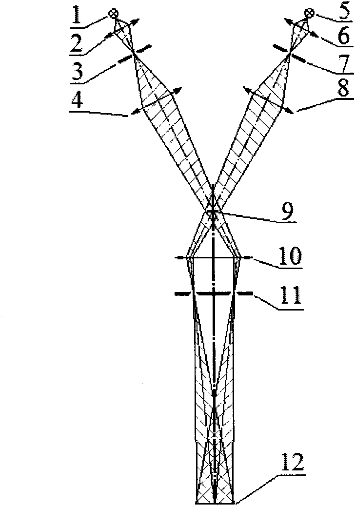
[0069] Such as figure 1 As shown, the high-magnification three-dimensional imaging microscope based on dual light source off-axis illumination provided by the present invention includes:

[0070] Two sets of light sources with the same structure on the left and right sides, the left light source includes a light bulb or LED light source 1, two sets of condenser lenses 2 and 4, and a pinhole diaphragm 3 between the two sets of condenser lenses; the right light source includes a light bulb or LED light source 5 in turn , two groups of condensers 6 and 8, and a pinhole diaphragm 7 between the two groups of condensers; the pinhole diaphragm is arranged on the exit pupil plane of the microscopic objective lens, and the center of the aperture diaphragm is between the optical axis of the illumination beam and the microscopic objective lens At the intersection of the exit pupil p...

Embodiment 2

[0075] Embodiment 2: High magnification three-dimensional imaging microscope (single lens light source)

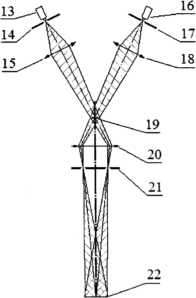
[0076] Such as figure 2 As shown, the left and right groups of light sources of the present invention can also be illuminated by monochromatic LEDs of the same structure, that is, the left light source includes a monochromatic LED light source 13, a pinhole diaphragm 14, and a group of condenser mirrors 15 in turn; the right light source sequentially It includes a monochromatic LED light source 16, a pinhole diaphragm 17 and a group of condenser lenses 18, and the rest of the structure is the same as that of Embodiment 1.

Embodiment 3

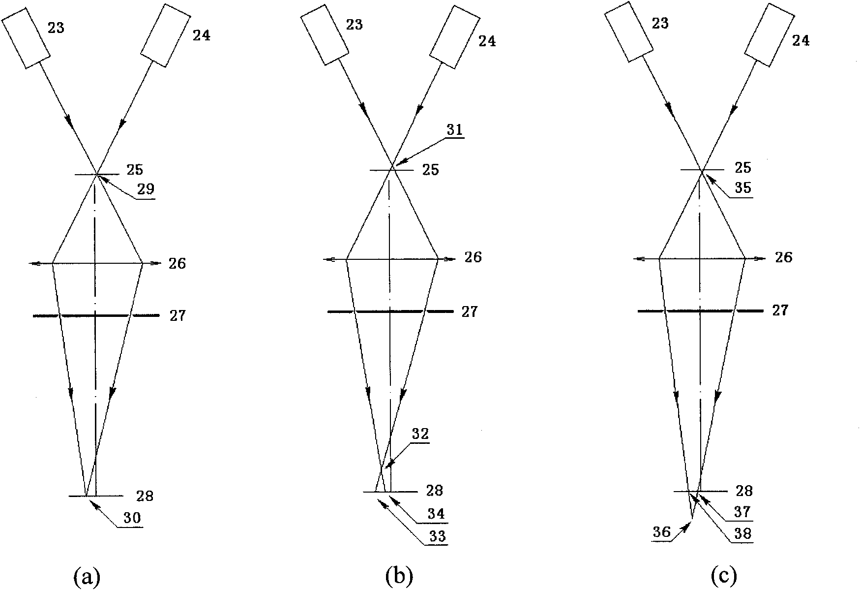
[0077] Embodiment 3: Imaging method for obtaining three-dimensional position information of an object with a three-dimensional imaging microscope

[0078] use the present invention figure 1 or figure 2 The shown device measures the three-dimensional coordinates of the object (the specific steps are as described in the summary of the invention), the left light source is illuminated by a red LED, the right light source is illuminated by a blue LED, the lateral magnification of the microscopic objective lens is 40 times, and the conjugate distance of the object image 195mm, NA=0.65, CCD effective imaging area 3.3mm×4.4mm, 1024×768 pixels.

[0079] 1. Use the reticle to calibrate the microscope

[0080] Adjust the reticle vertically to make the red and blue cross images overlap, determine the zero point of the z axis, take the zero point of the x and y axes on the axis corresponding to the center of the CCD, and move the reticle vertically, with a translation range of ±10 μm an...


PUM


Abstract

The invention discloses a high-magnification three-dimensional imaging microscope based on double-light source off-axis illumination and an imaging method and relates to a device for acquiring a left path of image and a right path of image by a CCD (Charge Coupled Device), a method for changing focus depth, a method for acquiring and separating two paths of images, a system calibrating method and a three-dimensional coordinate calculating method of a target. The three-dimensional imaging microscope mainly comprises a left off-axis light source, a right off-axis light source, a concentrated projecting assembly, a microobjective and a CCD, wherein the left off-axis light source and the right off-axis light source are symmetrical. The imaging method comprises the following steps of: calibrating the relation of microscope defocusing amount and double-image distance; acquiring an image; processing the image; recognizing a target; calculating a two-dimensional coordinate; and converting the two-dimensional coordinate into a three-dimensional coordinate. A left and right image synchronous acquiring method comprises a two-color method and a polarization method, and an asynchronous acquiring method comprises an LED switching illumination method. The three-dimensional coordinate of an object can be rapidly calculated. An illuminating light beam is converged on entrance pupils of the microobjective, the diameter of the light beam is limited by a variable diaphragm, and the focus depth is changed, thereby maintaining the illumination of the image surface to be basic invariant.

Description

【Technical field】: [0001] The invention belongs to the technical field of optical instruments, and relates to an imaging principle for real-time acquisition of high-magnification three-dimensional microscopic images, an image processing method and a three-dimensional coordinate calculation method. 【Background technique】: [0002] In the field of optical instruments, real-time acquisition and display of high-magnification stereoscopic microscopic images has always been one of the difficult problems for human beings to explore the microscopic world. In order to achieve high-precision, high-efficiency, and high-reliability operations on tiny objects, micro-manipulation robots have been invented. In the micro-manipulation robot system, the only way to feed back the three-dimensional position information is to obtain the microscopic image with three-dimensional position information through microscopic vision, and obtain the three-dimensional coordinates of the target through imag...

Claims


Application Information

Patent Timeline
IPC IPC(8): G02B21/06G02B21/36
Inventor 黄大刚赵新孙明竹车秀阁方勇纯张蕾卢桂章
Owner NANKAI UNIV
Why Eureka
Try Eureka