
Improved continuous variable-voltage and variable-frequency soft starter

A technology of soft starter and inverter, which is applied to the starter of a single multi-phase induction motor, motor generator/starter, etc. It can solve the problems of fewer stages and cannot meet the requirements of soft start, and achieve overload capacity strong effect

Inactive Publication Date: 2012-03-21
汪槱生
View PDF0 Cites 1 Cited by
  • Summary
  • Abstract
  • Description
  • Claims
  • Application Information

AI Technical Summary

Problems solved by technology

Although different connection methods of thyristors will produce a small number of different frequencies, but because the number of stages is too small, it often cannot meet the requirements of soft start.
Therefore, sometimes expensive frequency converters or hydraulic couplings have to be used instead of starters

Method used


Image

  • Improved continuous variable-voltage and variable-frequency soft starter
  • Improved continuous variable-voltage and variable-frequency soft starter
  • Improved continuous variable-voltage and variable-frequency soft starter

Examples


specific Embodiment 1

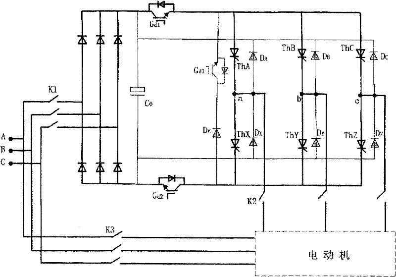
[0029] The soft starter used for the continuous variable frequency variable voltage of electric motor in specific embodiment 1 is as figure 1 shown.

[0030] The soft starter includes a mechanical switch K1 connected to the three-phase grid power supply, and also includes an inverter and two fully-controlled high-frequency electronic switches Gd 1 、Gd 2 A series circuit consisting of Gd 1 、Gd 2 respectively connected to the upper and lower ends of the series circuit, the series circuit and the capacitor C 0 The two ends connected in parallel to the output of a three-phase diode rectifier bridge; the mechanical switch K1 is connected to the input end of the three-phase diode rectifier bridge; the inverter consists of the following two parts:

[0031] (1) Six thyristors ThA, ThB, ThC, ThX, ThY, ThZ on the AC side of the inverter and six diodes D A 、D B 、D C 、D X 、D Y 、D Z 3 pairs of bridge arms together; each bridge arm contains a thyristor and an anti-parallel diode,...

specific Embodiment 2

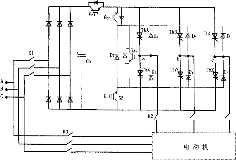
[0043] Such as image 3 As shown, the soft starter includes a mechanical switch K1 connected to the three-phase grid power supply, and also includes an inverter and a fully-controlled high-frequency electronic switch G d1 A series circuit composed of G d1 Connected to the upper end of the series circuit, the series circuit and the capacitor C 0 The two ends connected in parallel to the output of a three-phase diode rectifier bridge; the mechanical switch K1 is connected to the input end of the three-phase diode rectifier bridge; the inverter consists of the following two parts:

[0044] (1) Six thyristors ThA, ThB, ThC, ThX, ThY, ThZ on the AC side of the inverter and six diodes D A 、D B 、D C 、D X 、D Y 、D Z 3 pairs of bridge arms together; each bridge arm contains a thyristor and an anti-parallel diode, where: the cathode of ThA is connected to the anode of DA to become the upper bridge arm of the first pair of bridge arms, that is, the A bridge arm, ThX Anode and D X ...


PUM


Abstract

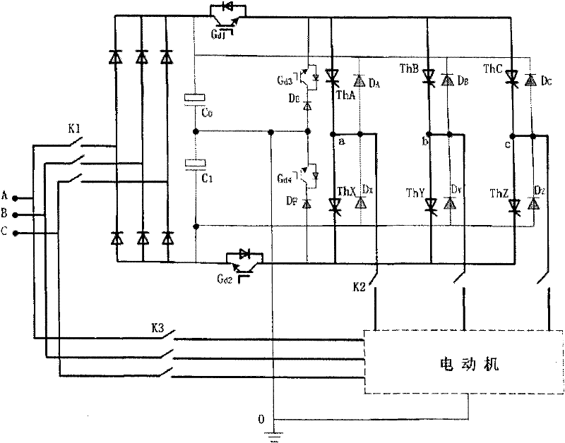
The invention relates to a power electronics control device and aims at providing an improved continuous variable-voltage and variable-frequency soft starter used for a motor. The soft starter comprises a mechanical switch K1 and a series circuit, wherein the series circuit comprises an inverter and full-control high-frequency electronic switches Gd1 and Gd2, and the series circuit and a capacitor C0 are connected in parallel with both ends of the output of a three-phase diode rectifier; a series switch circuit made by connecting a full-control high-frequency electronic switch Gd3 and a diodeDE in series is connected in parallel with both ends of the input of the inverter; and wires respectively from the middle points of three pairs of bridge arms of the inverter are connected with a three-phase asynchronous motor through a switch K2. The soft starter can change frequency and voltage continuously, so that the starting force of the motor is great while the starting current is not too great; the cost is reduced and the overload capacity is enhanced, so that the soft starter can be applicable to high-voltage occasions; and the three functions of regulating voltage, cutting off during failure and turning off an inverter thyristor can be realized by using a few full-control high-frequency elements, so that the full-control high-frequency elements work at high frequency while the thyristor works at low frequency.

Description

technical field [0001] The present invention relates to a power electronic control device, more specifically, the present invention relates to an improved continuous variable frequency variable voltage soft starter for electric motors. Background technique [0002] In the current industrial production and operation, because the current of the large motor is too large when it is started, it is difficult for the power grid to bear, so it is often necessary to add a set of soft starters. The commonly used soft starter is actually a set of step-down devices composed of thyristors. As the voltage decreases, although the starting current can be reduced, the starting torque is also greatly reduced, and it is difficult to start for heavier loads. It is best to reduce the frequency while reducing the voltage, because reducing the frequency can increase the magnetic field of the motor, thereby increasing the torque. From the perspective of reducing the impact on the power grid and i...

Claims


Application Information

Patent Timeline
Patent Type & Authority Patents(China)
IPC IPC(8): H02P1/30
Inventor 汪槱生
Owner 汪槱生
Learn More