LED driving method and LED driving circuit

A technology of light-emitting diodes and driving methods, which is applied to the layout of electric lamp circuits, light sources, electric light sources, etc., can solve the problems of low efficiency of light-emitting diodes and cannot be automatically adjusted, and achieve the effect of improving driving efficiency

Active Publication Date: 2010-12-01
AU OPTRONICS CORP
View PDF2 Cites 39 Cited by
  • Summary
  • Abstract
  • Description
  • Claims
  • Application Information

AI Technical Summary

Problems solved by technology

However, the current LED driving method has the following disadvantages: (a) the driving current of the LED is fixed and cannot be automatically adjusted according to the usage conditions; (b) the driving current is fixed at the maximum Use the current of the maximum gray scale brightness when using the brightness level, which will make the LED work in the lower efficiency area

Method used


Image

  • LED driving method and LED driving circuit
  • LED driving method and LED driving circuit
  • LED driving method and LED driving circuit

Examples


Embodiment Construction

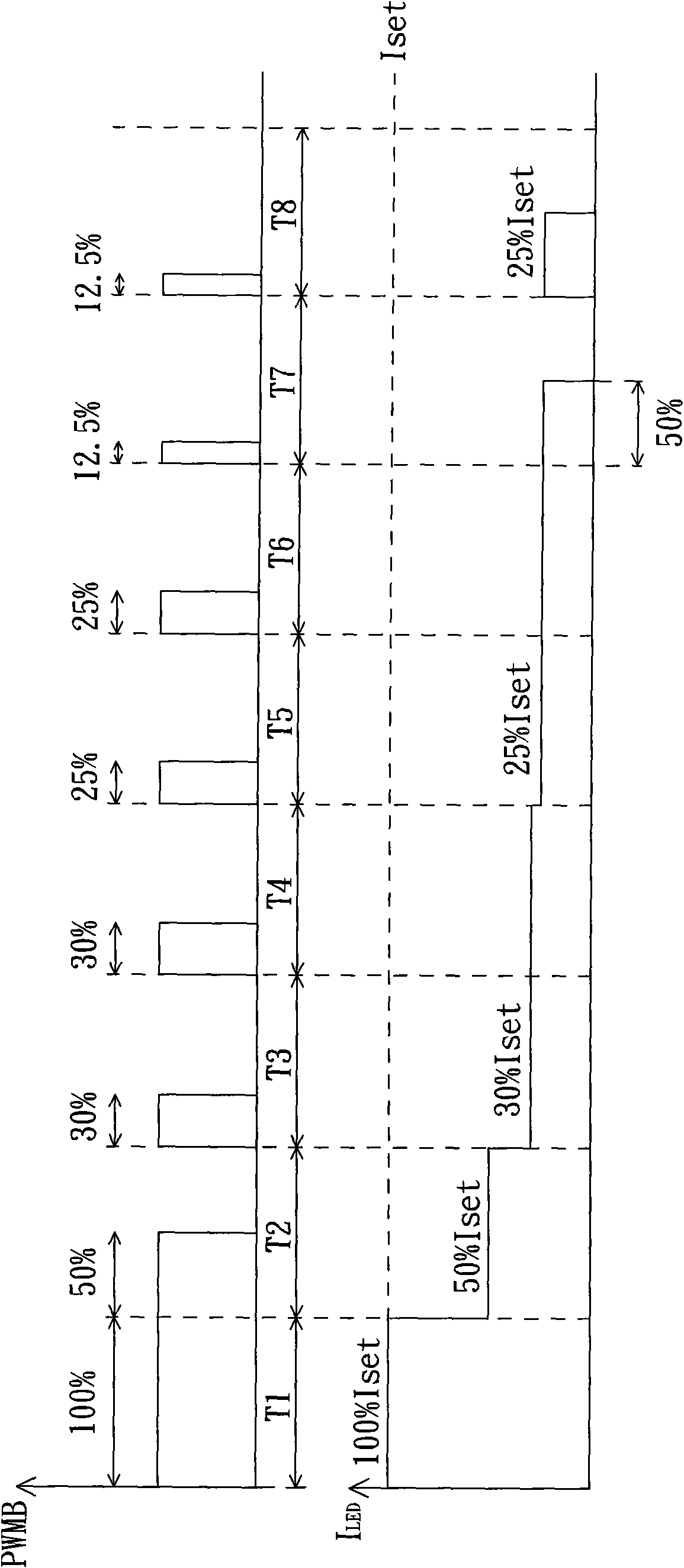
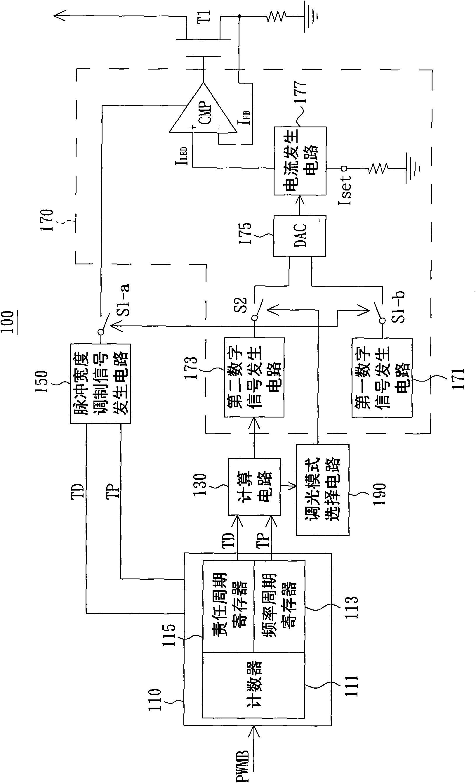
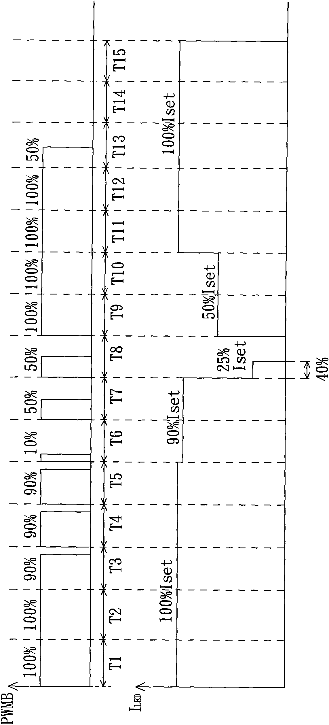
[0035] see figure 1 , which shows a timing diagram of a plurality of signals of a LED driving method according to an embodiment of the present invention. Here, the LED driving method in this embodiment can be applied to driving a backlight source of a non-self-illuminating display, but the present invention is not limited thereto. The following will combine figure 1 Each step of the light emitting diode driving method proposed by the embodiment of the present invention will be described in detail.

[0036] Specifically, the light emitting diode driving method of this embodiment may include the steps of: providing a pulse width modulation signal PWMB to determine the brightness of the light emitting diode, obtaining a duty cycle of the pulse width modulation signal PWMB, and according to the obtained duty cycle and the preset The relative size relationship of the critical value enables the LED to selectively work in the pulse width modulation dimming mode or the DC dimming mo...


PUM


Abstract

The invention relates to a LED driving method and an LED driving circuit. The LED driving method comprises the following steps of: providing a first PWM (Pulse Width Modulation) signal to decide the brightness of an LED; acquiring the duty cycle of the first PWM signal; and enabling the LED to selectively work in a PWM dimming mode or a DC dimming mode according to the relative value relation of the acquired duty cycle and a preset critical value. The dimming model of the LED is set according to the value of the duty cycle to control the brightness of the LED at two stages, i.e. the whole LEDdriving efficiency can be effectively improved by adopting a mixed dimming mode.

Description

technical field [0001] The invention relates to the technical field of light emitting diode driving, and in particular relates to a light emitting diode driving method and a light emitting diode driving circuit. Background technique [0002] Since the display panel of the non-self-illuminating display (for example: liquid crystal display) does not emit light itself, a backlight source is needed to provide backlighting for the display panel. At present, backlight sources can be roughly classified into cold cathode fluorescent lamps, hot cathode fluorescent lamps, light emitting diodes (LEDs) or other electroluminescent elements. Among them, light-emitting diodes are more and more widely used as backlight sources for liquid crystal displays due to their advantages such as high color saturation, no mercury, long life, low energy consumption, and adjustable color temperature through driving current. [0003] At present, in order to reduce the power consumption of the light-emit...

Claims


Application Information

Patent Timeline
Patent Type & Authority Applications(China)
IPC IPC(8): H05B37/02
CPCY02B20/42Y02B20/40
Inventor 李弘庆余景州许胜凯王登科
Owner AU OPTRONICS CORP
Why Eureka
Try Eureka