Method and apparatus in pneumatic material conveying system

A conveying system and equipment technology, applied in conveyors, transportation and packaging, conveying bulk materials, etc., can solve the problems of increasing system complexity and cost, dust, fine particles, etc., to achieve easy and effective cleaning and processing, and minimum energy consumption the effect of reducing noise problems

Inactive Publication Date: 2010-12-01
MARICAP OY
View PDF3 Cites 7 Cited by
  • Summary
  • Abstract
  • Description
  • Claims
  • Application Information

AI Technical Summary

Problems solved by technology

Vacuum conveying systems usually contain the following problems in particular: high energy consumption, high air flow in the pipe, noise in the outlet pipe, problems with dust and fine particles
Also, large systems require multiple separate make-up air valves, adding to system complexity and cost
Also, cleaning of the transfer line is important, so cleaning of the transfer system (often comprising multiple separate branch pipes) is cumbersome
Known constructions do not allow for quick and cost-effective cleaning of transfer lines

Method used


Image

  • Method and apparatus in pneumatic material conveying system
  • Method and apparatus in pneumatic material conveying system
  • Method and apparatus in pneumatic material conveying system

Examples


Embodiment Construction

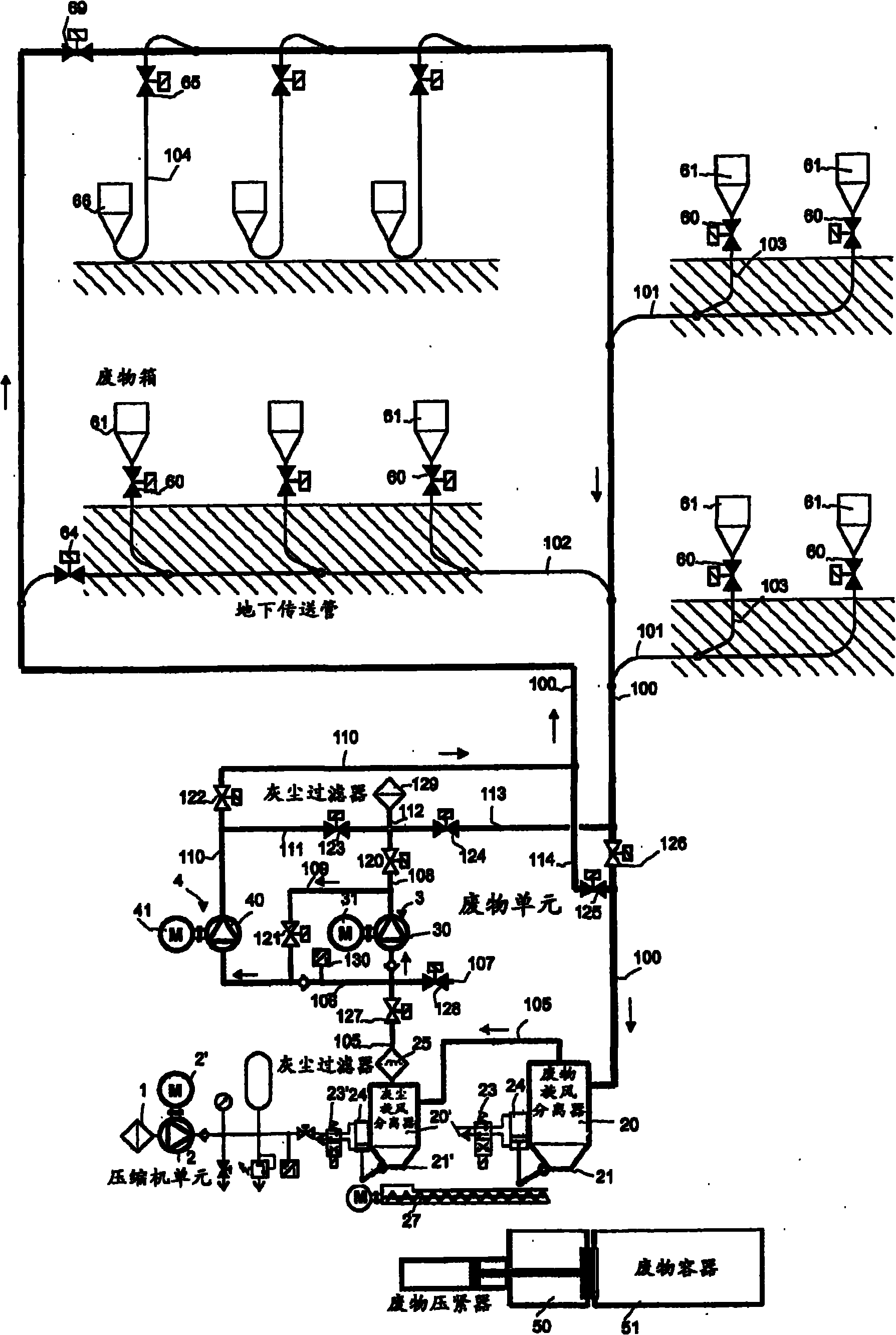
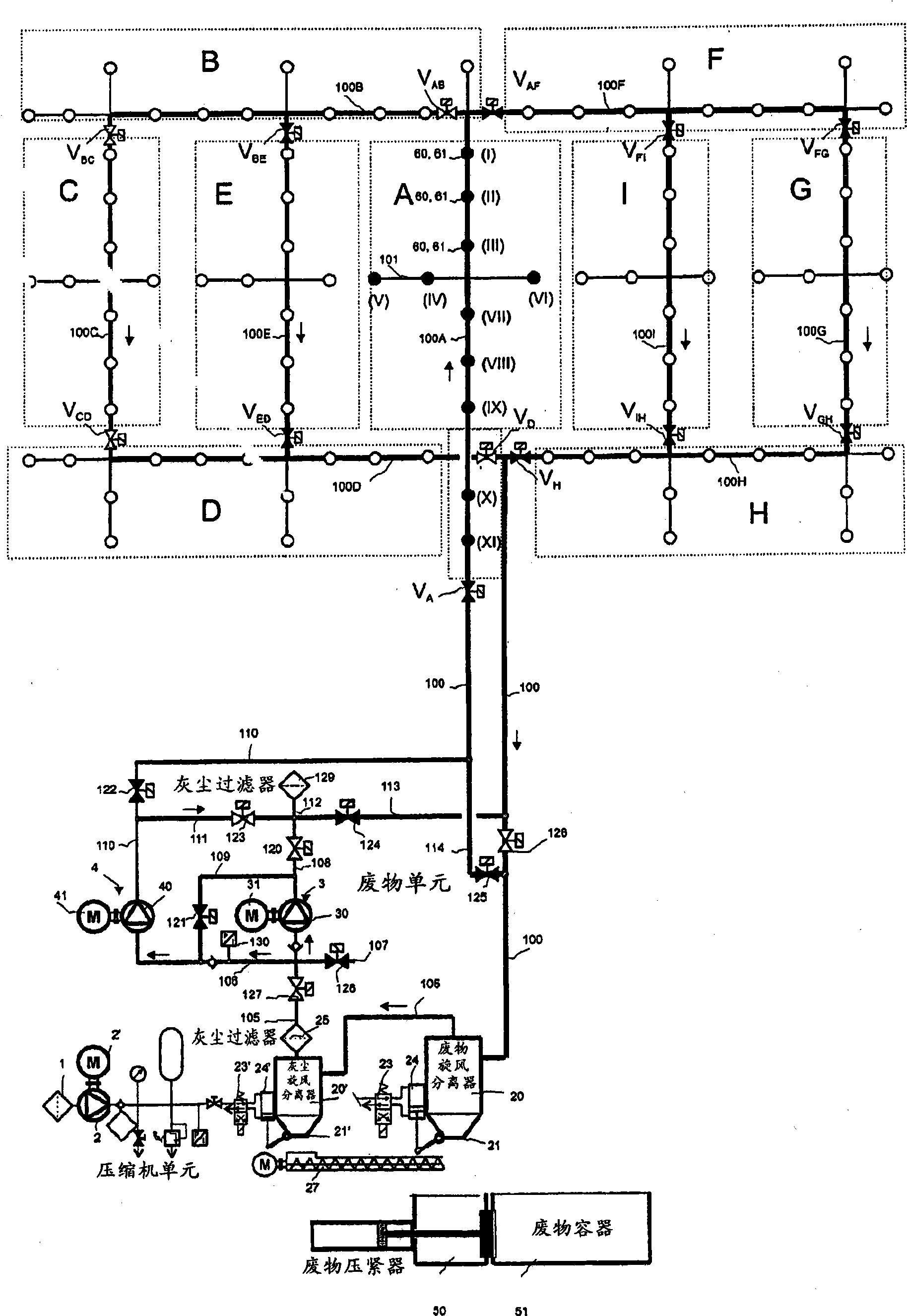
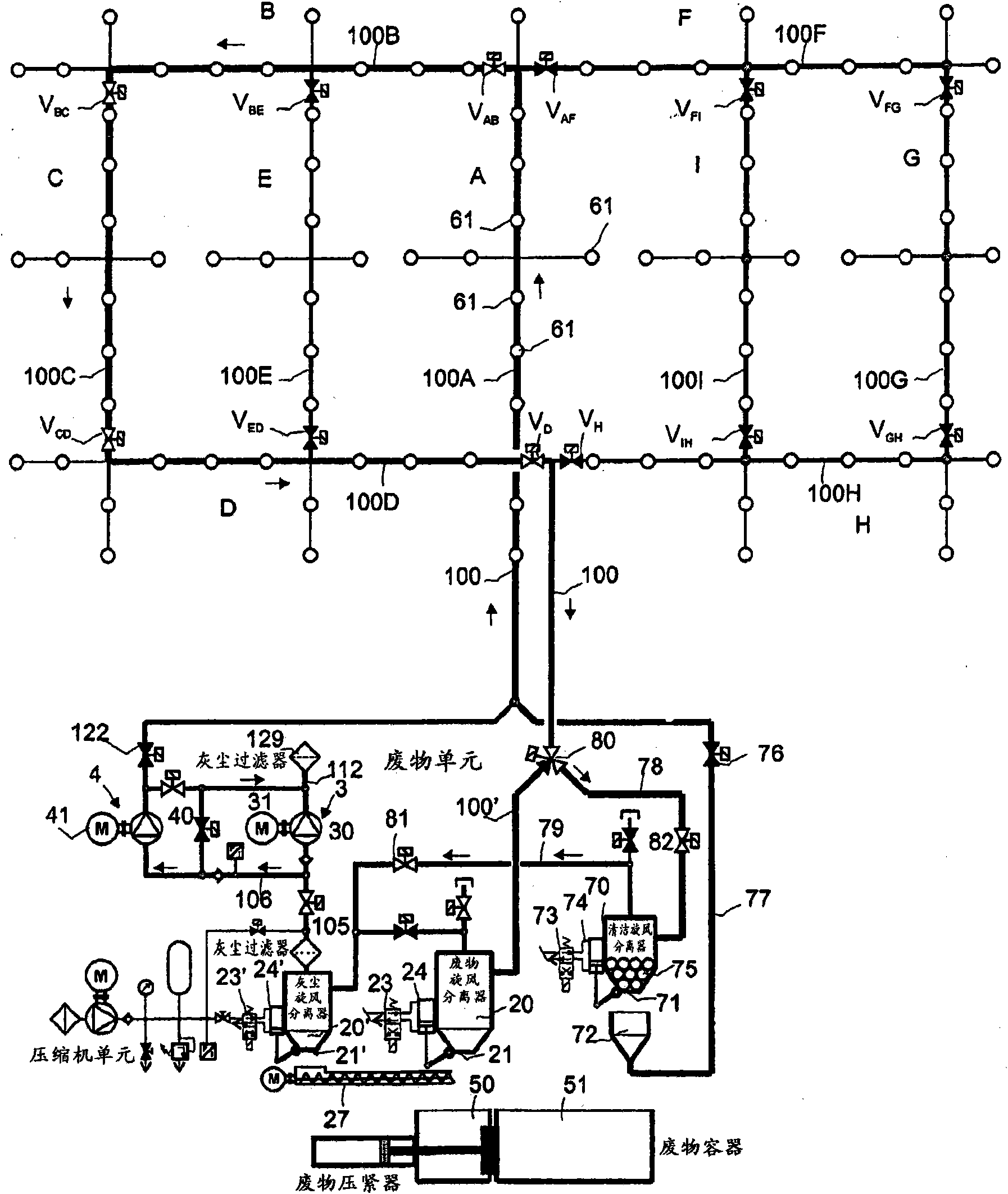
[0018] exist figure 1 In , reference numerals 61, 66 denote supply stations for materials to be conveyed, in particular waste materials, from which stations material to be conveyed, in particular waste materials such as household waste, will be supplied to the conveying system. The system may comprise a plurality of supply stations 61 , 66 from which the material to be conveyed is supplied to the conveying lines 100 , 101 , 102 , 103 , 104 . Typically, the transfer pipeline includes a main transfer pipe 100 into which a plurality of branch transfer pipes 101, 102 can be connected and to which a plurality of supply stations 61, 66 can in turn be connected via supply pipes 103, 104. In the delivery tube 100. The supplied material is conveyed along the conveying lines 100, 101, 102, 103, 104 to a separator device 20 in which the conveyed material is separated from the conveying air, eg due to falling velocity and centrifugal force. The separated material is removed from the sep...


PUM


Abstract

A method in a pneumatic material conveying system, such as a waste conveying system, which conveying system comprises at least one feed point (61) of material, particularly of waste material, a material conveying pipe (100) which is connectable to the feed point (61), a separator device (20) in which the material being conveyed is separated from conveying air, and means (3, 4) for providing a pressure difference in the conveying pipe (100) at least during the conveyance of the material. At least a part of the conveying piping (100) is connectable as a section of a circuit in which conveying air is circulated at least during the conveyance of the material with at least one first pump device, such as a vacuum unit (3), and with at least one second pump device, such as a blower unit (4).

Description

technical field [0001] The invention relates to a method according to the preamble of claim 1 . [0002] The invention also relates to a device according to claim 15 . [0003] The present invention relates generally to pneumatic conveying systems, such as vacuum conveying systems, and in particular to collecting and conveying waste, such as conveying household waste. More specifically, the present invention relates to cleaning the transfer tubes of such material transfer systems. Background technique [0004] Systems are known in which waste is conveyed in pipes by suction. In these systems, waste is transported long distances in pipelines by suction. The device is particularly useful for conveying waste in different establishments. Usually, a vacuum device is used to obtain the pressure difference, in which vacuum device, a vacuum generator, such as a vacuum pump or an ejector device, is used to provide a negative pressure in the transfer pipe. There is usually at lea...

Claims


Application Information

Patent Timeline
Patent Type & Authority Applications(China)
IPC IPC(8): B65G53/52B65G53/34
CPCB65G53/24B65F5/005B65G53/66B65G53/04
Inventor G·松德霍尔姆
Owner MARICAP OY
Why Eureka
Try Eureka