Variable inductor

一种可变、电容器的技术,应用在电气元件、模拟电抗的网络、阻抗网络等方向,能够解决压控晶体振荡器调谐范围限制、减小谐振频率、收益减小等问题

Active Publication Date: 2010-12-01
ACP ADVANCED CIRCUIT PURSUIT AG
View PDF6 Cites 9 Cited by
  • Summary
  • Abstract
  • Description
  • Claims
  • Application Information

AI Technical Summary

Problems solved by technology

[0005] The dynamic capacitance C in this resonator s Usually less than the capacitor capacitance C p several orders of magnitude, as can be seen from equation (1), increasing C p For reducing the resonant frequency f p has limited effect due to the ceramic or crystal resonator housing causing the C p The fixed part is usually quite large, towards C p Further addition of variable capacitance results in a diminishing gain in terms of relative frequency change (the square root on the right simply tends to 1)
Therefore, the tuning range of a voltage controlled crystal oscillator (VCXO) is typically limited

Method used


Image

  • Variable inductor
  • Variable inductor
  • Variable inductor

Examples


Embodiment Construction

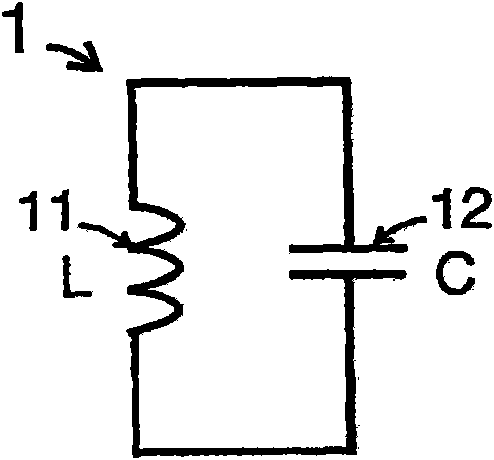
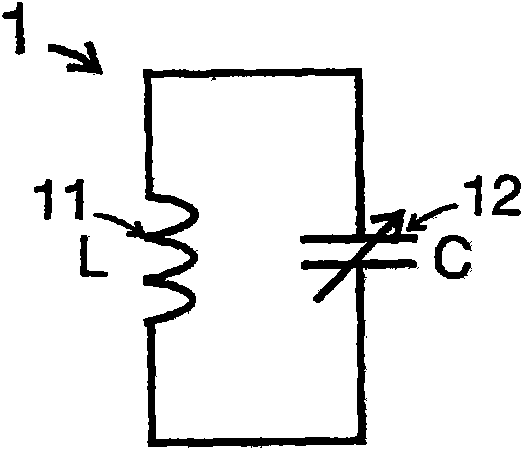
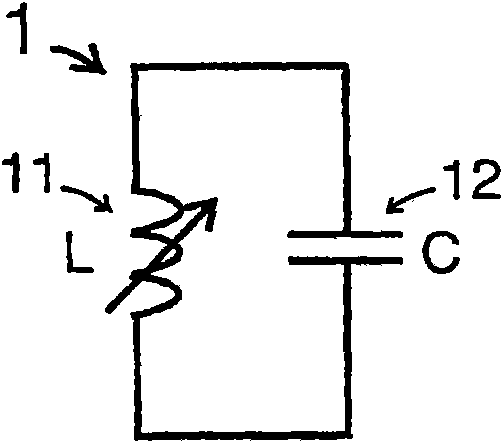
[0035] image 3 The circuit according to the first aspect of the invention is Figure 2c A modified version of the resonator circuit shown. Variable inductor L p with C p connected in parallel. The final combined admittance is at or near its resonant frequency f p , given by equation (2). In the equivalent capacitance C p ’ less than C p , as long as C p ’ is positive, the combined impedance is capacitive. Therefore, when used in a VCXO, the resulting smaller equivalent parallel capacitance extends the tuning range of the VCXO.

[0036] Y p = j 2 π f p C p + 1 j 2 π f p L p = j 2 π f p ( ...


PUM


Abstract

A variable simulated inductor comprises an integrator connected to receive the voltage across the input to the circuit. The output of the inductor is connected to a control terminal of a transconductor connected across the input of the circuit. The gain of the transconductor is electronically controllable in order to control the inductance of the circuit. An oscillator using a variable simulated inductor and a piezoelectric resonator connected in parallel is also provided.

Description

technical field [0001] The present invention relates to an electronically controlled variable inductor which finds wide application in analog and radio frequency integrated circuits including voltage controlled oscillators. Background technique [0002] The combination of an inductor and a capacitor in a loop (often called a resonant circuit) is an important part of an electronic circuit. For example, oscillators, filters, and impedances at the input or output of a radio frequency (RF) amplifier take advantage of the high-frequency selective properties of a resonant circuit to generate, boost, or cancel signals at specific frequencies. Figure 1a A well known resonant circuit 1 is shown comprising an inductor 11 and a capacitor 12 in the loop. The resonant frequency at which the total impedance of the surrounding loop is zero is inversely proportional to the square root of the product of the inductance L and the capacitance C. In many applications, such as tunable filters a...

Claims


Application Information

Patent Timeline
Patent Type & Authority Applications(China)
IPC IPC(8): H03H11/48
CPCH03H11/48H03H11/486H03H11/485
Inventor 黄秋庭
Owner ACP ADVANCED CIRCUIT PURSUIT AG
Why Eureka
Try Eureka