Nitrogen making machine with three-tower structure

A nitrogen generator and working tower technology, applied in the direction of nitrogen purification/separation, can solve the problems of low use efficiency of molecular sieve, large gas production capacity of nitrogen generator, low gas production efficiency, etc., to achieve stable overall purity and improve production efficiency. , The effect of stable air supply pressure

Active Publication Date: 2010-12-08
HANGZHOU SHENGDA MECHANICAL & ELECTRICAL HI TECH CO LTD
View PDF0 Cites 3 Cited by
  • Summary
  • Abstract
  • Description
  • Claims
  • Application Information

AI Technical Summary

Problems solved by technology

[0003] The present invention aims to solve the problems that the gas production capacity of the current two-tower structure nitrogen production process is small, the actual gas production efficiency of the four-tower structure nitrogen production process is low, and the use efficiency of molecular sieves is low. Therefore, a three-tower structure nitrogen production process of the present invention is provided. Machine, this kind of nitrogen generator has large gas production capacity and low production cost

Method used


Image

  • Nitrogen making machine with three-tower structure
  • Nitrogen making machine with three-tower structure
  • Nitrogen making machine with three-tower structure

Examples


Embodiment Construction

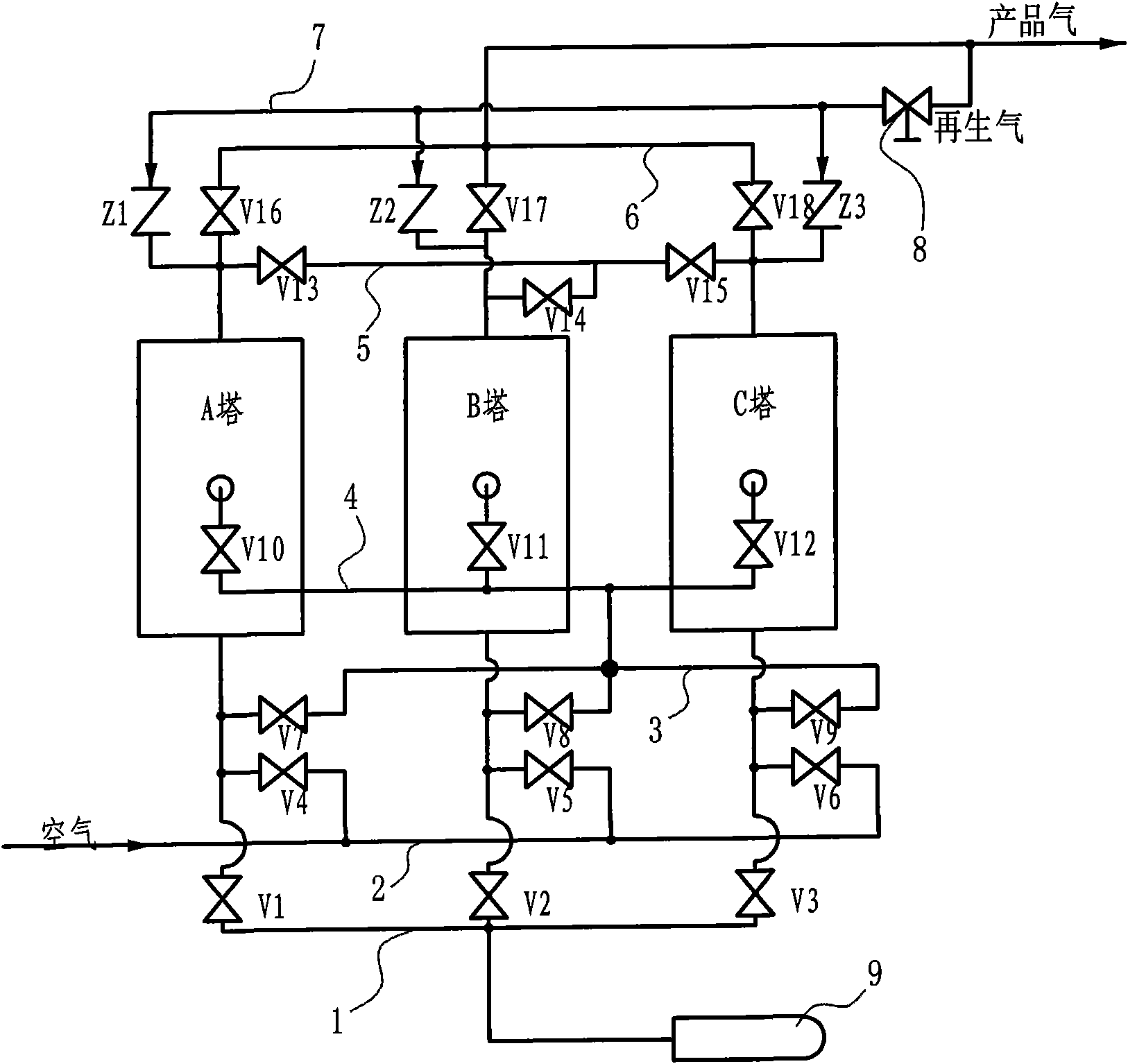
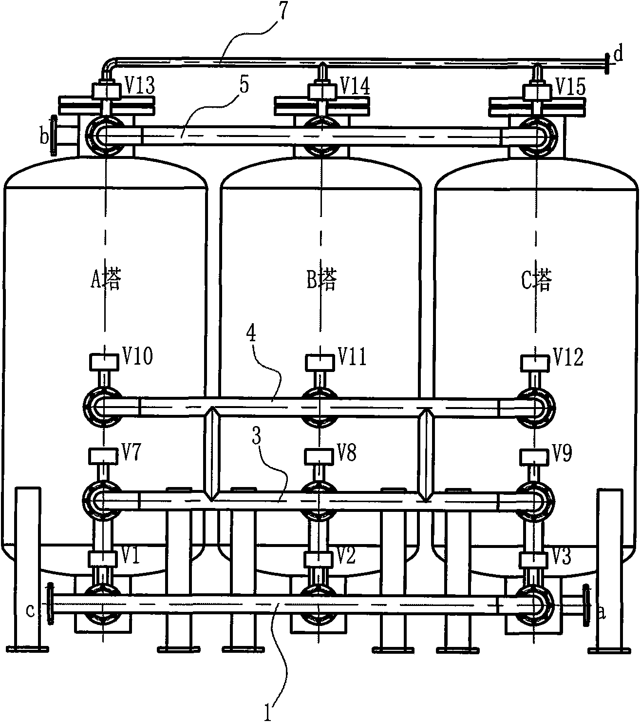
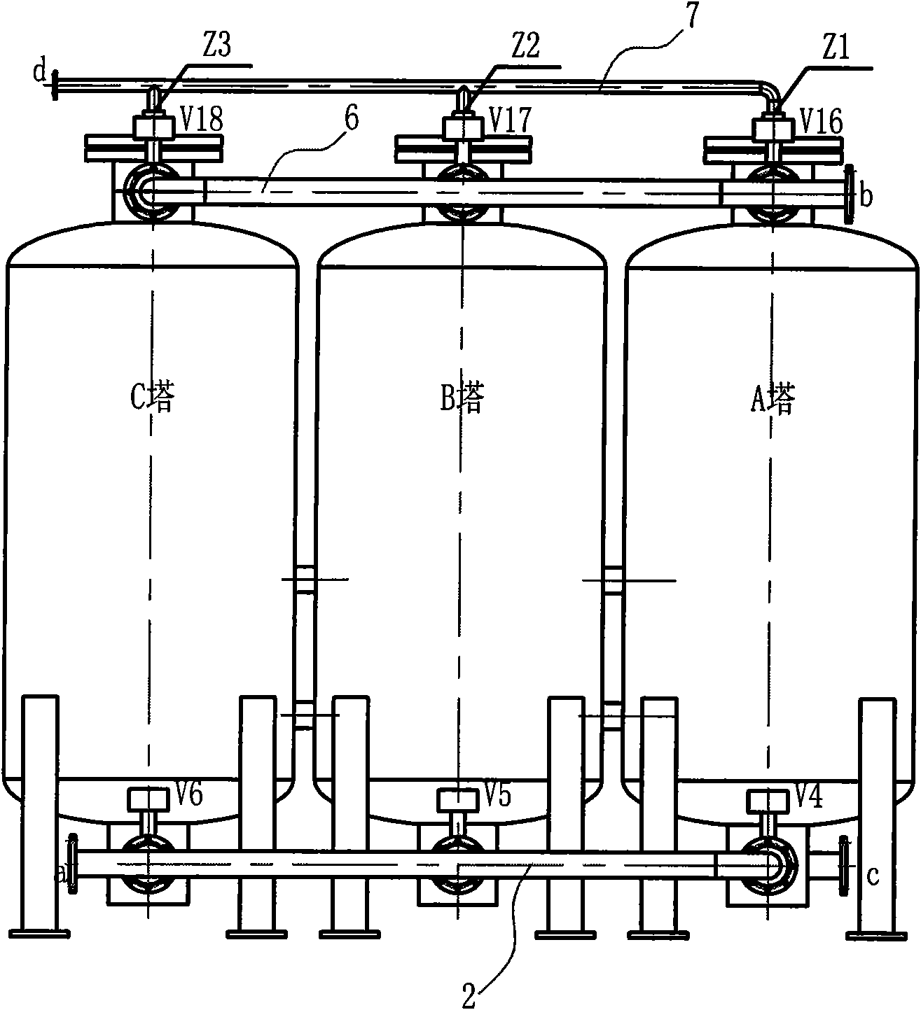
[0024] The three-tower structure nitrogen generator has a working tower with a built-in molecular sieve. The working towers are tower A, tower B and tower C. The bottom of tower A is connected in parallel with valve one V1, valve four V4 and valve seven V7. The bottom of tower B is connected in parallel. Valve 2 V2, valve 5 V5, and valve 8 V8 are connected in parallel through connecting pipes. The bottom of tower C is connected in parallel with valve 3 V3, valve 6 V6 and valve 9 V9 through connecting pipes. The other ends of valve 1, valve 2 and valve 3 are connected to pipe 1. The other ends of valve four, valve five and valve six are connected with pipe two and two, and the other ends of valve seven, valve eight and valve nine are connected with pipe three and three; the middle parts of tower A, tower B and tower C are respectively connected to the outside through connecting pipes There are valve 10 V10, valve 11 V11, valve 12 V12, the other end of valve 10, valve 11, and val...


PUM


Abstract

The invention provides a nitrogen making machine with a three-tower structure, which has reasonable structure and high efficacy. The nitrogen making machine is provided with a tower A, a tower B and a tower C, wherein the bottom of the tower A is provided with a valve 1, a valve 4 and a valve 7 in parallel; the bottom of the tower B is provided with a valve 2, a valve 5 and a valve 8 in parallel,and the bottom of the tower C is provided with a valve 3, a valve 6 and a valve 9; the middle parts of the tower A, the tower B and the tower C are respectively externally connected with a valve 10, a valve 11 and a valve 12; the top of the tower A is provided with a valve 13 and a valve 16 in parallel, the top of the tower B is provided with a valve 14 and a valve 17 in parallel, and the top of the tower C is provided with a valve 15 he a valve 18 in parallel; the other ends of the valve 13, the valve 14 and the valve 15 are connected with a pipe 5, the other ends of the valve 16, the valve 17 and the valve 18 are connected with a pipe 6; the tops of the tower A, the tower B and the tower C are respectively connected with a check valve 1, a check valve 2 and a check valve 3 and the otherends of the check valve 1, the check valve 2 and the check valve 3 are connected with a pipe 7; and a pipe 2 is provided with an air inlet, and a pipe 3 and a pipe 4 are bypassed mutually. The invention is suitable for serving as oxygen manufacture equipment with larger flow requirement.

Description

technical field [0001] The invention relates to a pressure swing adsorption nitrogen generator. Background technique [0002] With the continuous maturity of PSA (Pressure Swing Absorb<Pressure Swing Adsorption>) technology, the requirements for PSA nitrogen production are becoming more and more extensive. Currently, two-tower structures are commonly seen in this field, and some equipment that requires a relatively large volume flow generally have a four-tower structure. However, most of this four-tower structure equipment is actually a combination of two equipment with a two-tower structure. It is The two air inlets are combined into one pipeline, and the two air outlets are combined into one pipeline to realize, and its principle and working mode are still the same as those of the two-tower structure. Another aspect, if the large cubic equipment really needs to be made with two towers, there is a very disadvantage, that is, the aspect ratio of the equipment cylinder...

Claims


Application Information

Patent Timeline
Patent Type & Authority Applications(China)
IPC IPC(8): C01B21/04
Inventor 赵冲赵国大吴永刚
Owner HANGZHOU SHENGDA MECHANICAL & ELECTRICAL HI TECH CO LTD
Why Eureka
Try Eureka