Centralized lubricating system

A centralized lubricating and lubricating pump technology, which is applied in lubricating parts, engine lubricating, lubricating oil control valves, etc., can solve the problem of incomplete pressure relief, achieve the effects of simplifying the structure, avoiding excessive return, and facilitating production and processing

Active Publication Date: 2010-12-08
AUTOL TECH
View PDF3 Cites 3 Cited by
  • Summary
  • Abstract
  • Description
  • Claims
  • Application Information

AI Technical Summary

Problems solved by technology

[0003] The purpose of the present invention is to provide a centralized lubrication system to solve the problem of incomplete pressure relief in the existing volumetric centralized lubrication system

Method used


Image

  • Centralized lubricating system
  • Centralized lubricating system
  • Centralized lubricating system

Examples


Embodiment 2

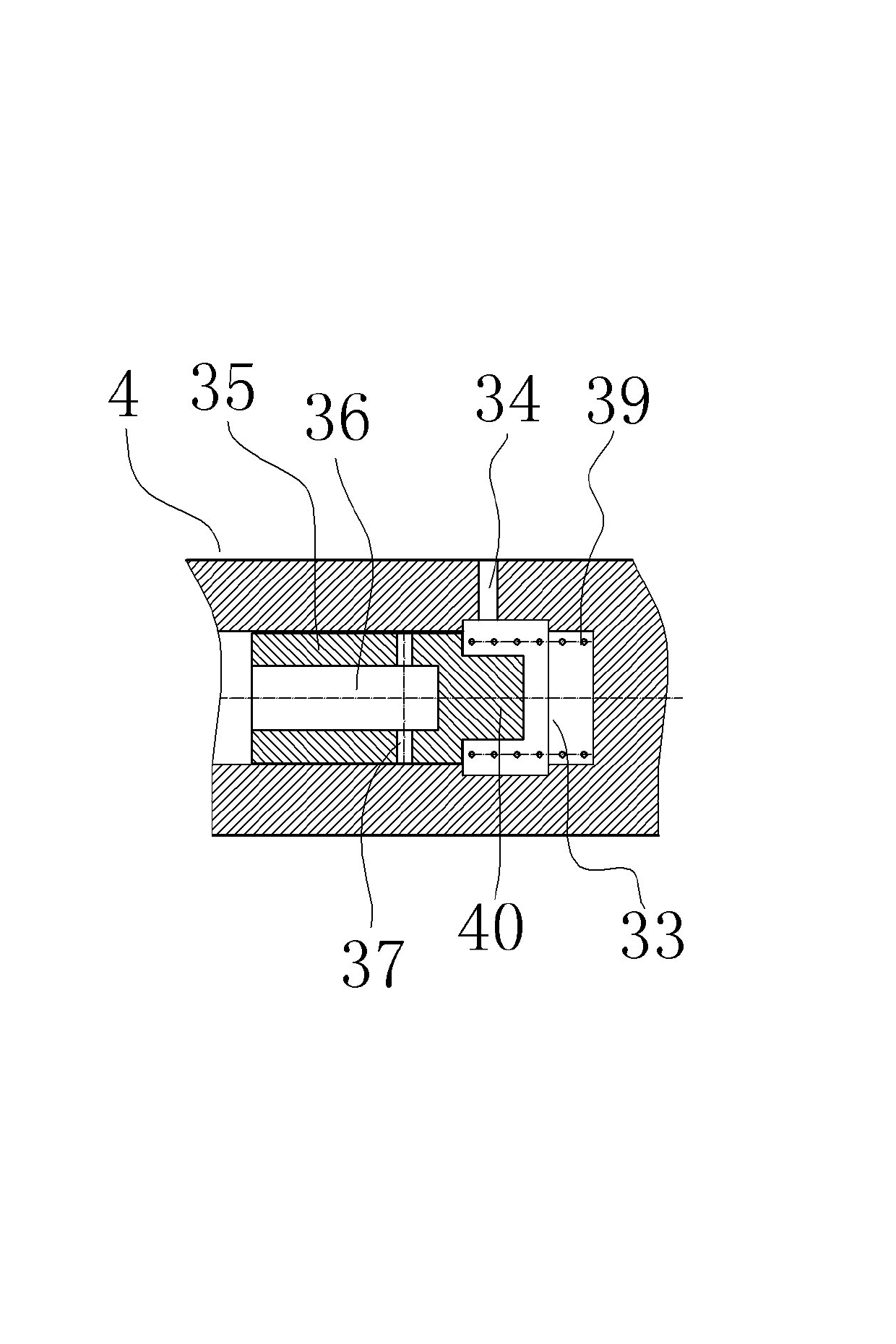
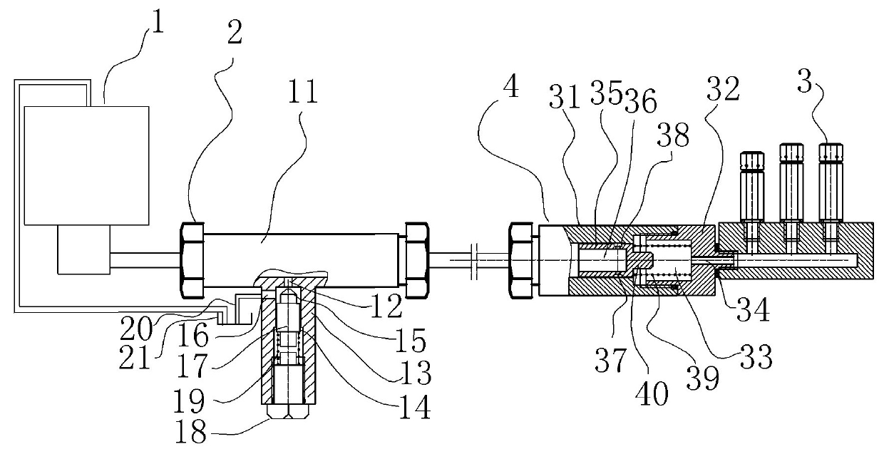
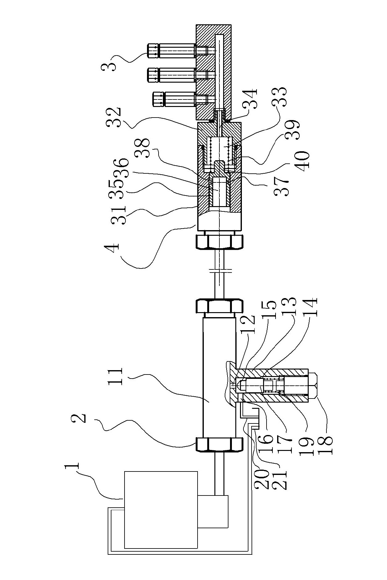
[0023] Embodiment 2 of the present invention, such as figure 2 As shown, the difference between this embodiment and embodiment 1 is that the difference between this embodiment and embodiment 1 is only that the auxiliary valve body body 1 has a useful The pressure relief spring 39 is top mounted between the auxiliary valve core 35 and the mating body 32 because of the limiting shoulder 41 constraining the return stroke of the auxiliary valve core 35 (of course, in other embodiments, a circlip may also be used).

[0024] Embodiment 3 of the auxiliary pressure relief valve of the present invention, such as image 3 As shown, the difference between this embodiment and Embodiment 1 is that the auxiliary valve body is a cylindrical structure with one end open, the inner hole of the auxiliary valve body is a stepped hole, and the pressure relief spring 39 is arranged between the auxiliary valve core 35 and the auxiliary valve body. Between the sealing ends, the oil outlet hole 34 i...


PUM


Abstract

The invention relates to a centralized lubricating system which comprises a lubricating pump, a pump unloading valve and an oil separator, wherein at least one auxiliary pressure relief valve is arranged between the pump unloading valve and the oil separator. As the auxiliary pressure relief valve is arranged between the pump unloading valve and the oil separator, the centralized lubricating system can rapidly and thoroughly reduce the pressure at an inlet of the oil separator in a pipeline of the centralized lubricating system, thus ensuring the smooth oil injection of the oil separator.

Description

technical field [0001] The invention relates to the technical field of lubrication, in particular to a centralized lubrication system. Background technique [0002] Volumetric centralized lubrication technology has been widely used in the field of lubrication technology due to its high reliability, precise oil discharge, low cost and low pressure requirements for lubrication pumps and pipeline systems. In order to ensure the normal operation of the distributor of volume pressure relief centralized lubrication, this technology requires that after the operation of the lubricating pump, the oil pressure near the oil separator group in the main oil circuit must be completely removed, so that the oil separator can supply oil to each lubrication point. Therefore, in this structure, a pump unloading valve is set at the oil outlet of the pump in the fuel tank. After the system stops running, the pressure relief port will automatically open, and the oil in the main pipeline will auto...

Claims


Application Information

Patent Timeline
Patent Type & Authority Applications(China)
IPC IPC(8): F16N7/38F16N23/00
Inventor 赵大平和兆乐王德全
Owner AUTOL TECH
Why Eureka
Try Eureka