Check patentability & draft patents in minutes with Patsnap Eureka AI!

Band gap circuit

A circuit and current path technology, applied in the direction of logic circuit connection/interface layout, adjustment of electrical variables, instruments, etc.

Inactive Publication Date: 2010-12-08
AICESTAR TECH SUZHOU CORP
View PDF0 Cites 6 Cited by
  • Summary
  • Abstract
  • Description
  • Claims
  • Application Information

AI Technical Summary

Problems solved by technology

The voltage boost circuit provides a boosted voltage with a single current path

Method used


Image

  • Band gap circuit
  • Band gap circuit
  • Band gap circuit

Examples


Embodiment Construction

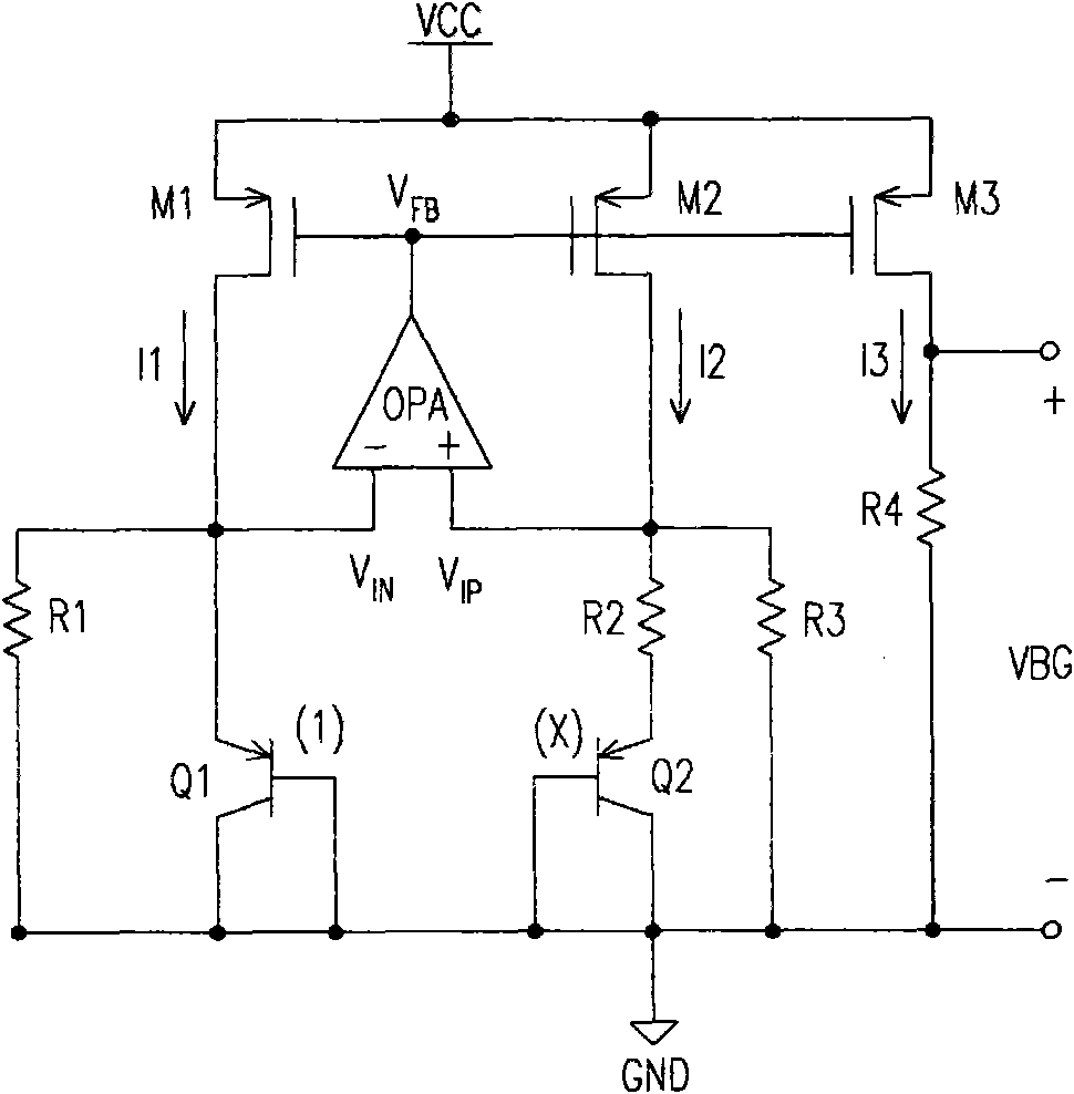
[0034] Figure 5 It is a schematic diagram of a bandgap circuit according to an embodiment of the present invention. Figure 5 The bandgap circuit includes a current source 510 , a voltage equalization circuit 520 , a voltage input circuit 530 , a voltage boost circuit 540 , and a voltage output circuit 550 . The current source 510 provides three currents I1, I2 and I3, and maintains the current magnitudes of these three currents in a fixed mutual ratio; for example, the currents I1, I2 and I3 can be equal to each other, that is, the current I1:I2 :I3=1:1:1. The voltage boost circuit 540 provides a boosted voltage V through a single current path G . The voltage input circuit 530 is connected to the voltage boost circuit 540 , the voltage equalization circuit 520 and the current source 510 . The voltage input circuit 530 receives the currents I1 and I2, and boosts the voltage V G based on the input voltage V IN and V IP . The voltage equalization circuit 520 is connecte...


PUM


Abstract

The invention discloses a band gap circuit, which comprises a current source, a voltage boosting circuit, a voltage input circuit, a voltage equalizing circuit and a voltage output circuit. The current source provides a first current, a second current and a third current which are equal. The voltage boosting circuit provides a boosting voltage by means of a current path. The voltage input circuit is connected with the voltage boosting circuit and the current source to receive a first and a second currents and provides a first input voltage and a second input voltage based on the boosting voltage respectively. The voltage equalizing circuit is connected with the voltage input circuit and receives the first and the second input voltages and ensures that the first input voltage is equal to the second input voltage. The voltage output circuit is connected with the current source and provides a band gap reference voltage according to the third current.

Description

technical field [0001] The present invention relates to a bandgap circuit, in particular to a current mode and a voltage mode bandgap circuit. Background technique [0002] A bandgap circuit is used to generate a stable reference voltage that is not affected by temperature. figure 1 It is a circuit diagram of a current mode bandgap circuit in the prior art. Metal oxide semiconductor field effect transistors (Metal Oxide Semiconductor Field Effect Transistor, MOS transistors for short) M1 , M2 and M3 form a current mirror to make the currents I1 , I2 and I3 equal to each other. The two input terminals of the operational amplifier OPA respectively receive the input voltage V IN and V IP , the virtual short circuit effect of the operational amplifier makes V IN equal to V IP . Resistors R1 and R3 have the same resistance value, and V IN equal to V IP , so the currents flowing through R1 and R3 are the same, and thus the currents flowing through bipolar transistors (Bipo...

Claims


Application Information

Patent Timeline
IPC IPC(8): G05F3/16H03K19/0175
Inventor 汪岭
Owner AICESTAR TECH SUZHOU CORP
Features
  • R&D
  • Intellectual Property
  • Life Sciences
  • Materials
  • Tech Scout
  • Unparalleled Data Quality
  • Higher Quality Content
  • 60% Fewer Hallucinations
Learn More