
Full-automatic pipe cutting machine

A fully automatic, cutting machine technology, applied in the field of pipe processing, can solve the problems of slow cutting speed, short tool life, low cutting accuracy, etc., and achieve the effect of improving processing accuracy, prolonging service life and saving labor.

Inactive Publication Date: 2010-12-15
周志玉 +1
View PDF6 Cites 23 Cited by
  • Summary
  • Abstract
  • Description
  • Claims
  • Application Information

AI Technical Summary

Problems solved by technology

[0002] Pipes are used in various production and manufacturing fields. Most of the equipment used to cut pipes in the past is in the form of a single cutting piece, which cuts the pipe through the rotation of the cutting piece. This processing method has low cutting accuracy, slow cutting speed and high labor intensity. , It is also not conducive to environmental protection, so a processing method that uses multiple cutting blades arranged radially to cut the pipe at the same time appeared. When cutting, the position of the cutting blade relative to the pipe is fixed, and the cutting blade rotates. The cutting piece moves radially to cut the pipe. Although this cutting method improves the work efficiency and reduces the labor intensity, the section of the cut pipe is relatively rough, and burrs are easy to form on the end surface, which is easy to cause the pipe to be damaged during the cutting process. Deformation occurs and the service life of the tool is shortened

Method used


Image

  • Full-automatic pipe cutting machine
  • Full-automatic pipe cutting machine
  • Full-automatic pipe cutting machine

Examples


Embodiment Construction

[0016] The present invention will now be further described in conjunction with the accompanying drawings and embodiments. These drawings are all simplified schematic diagrams, which only illustrate the basic structure of the present invention in a schematic manner, so they only show the configurations related to the present invention.

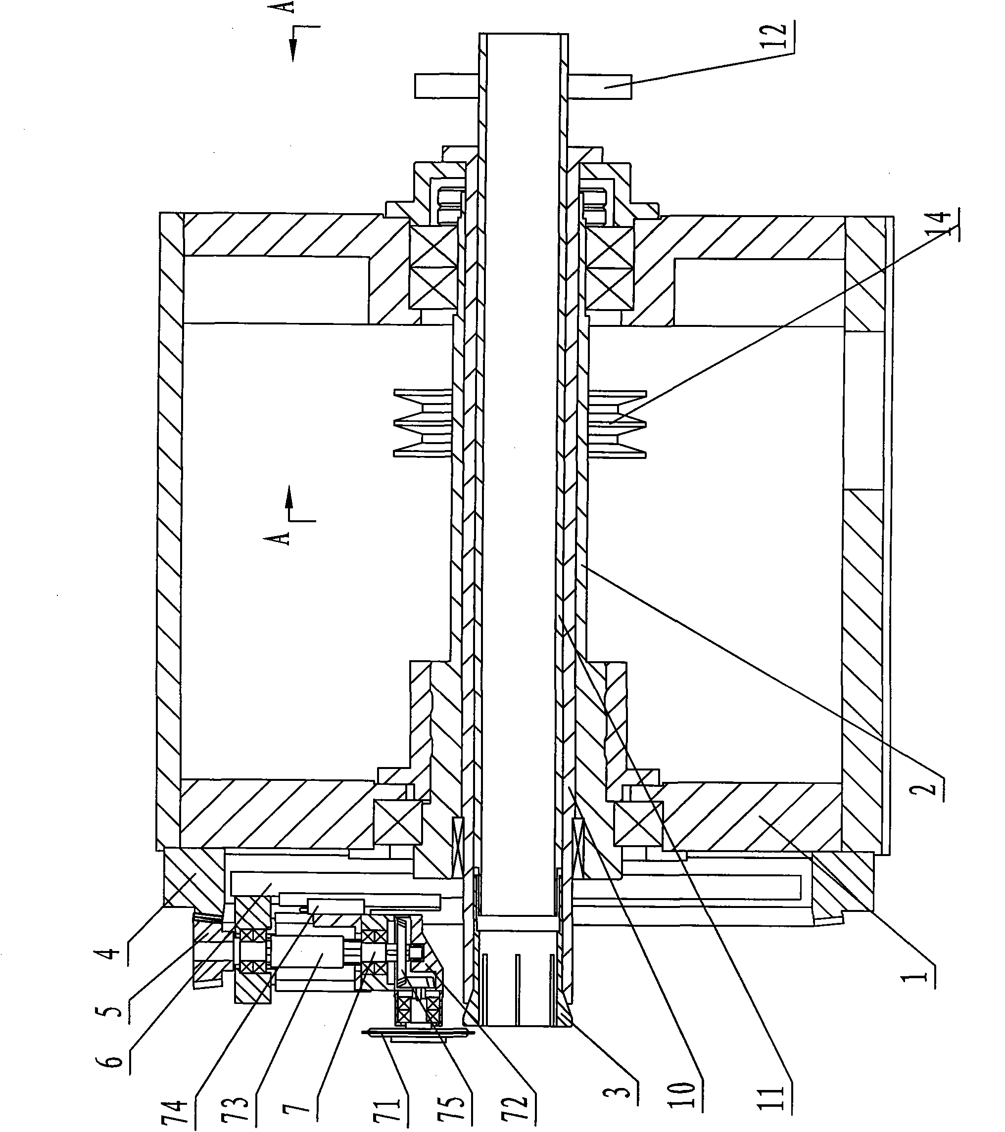
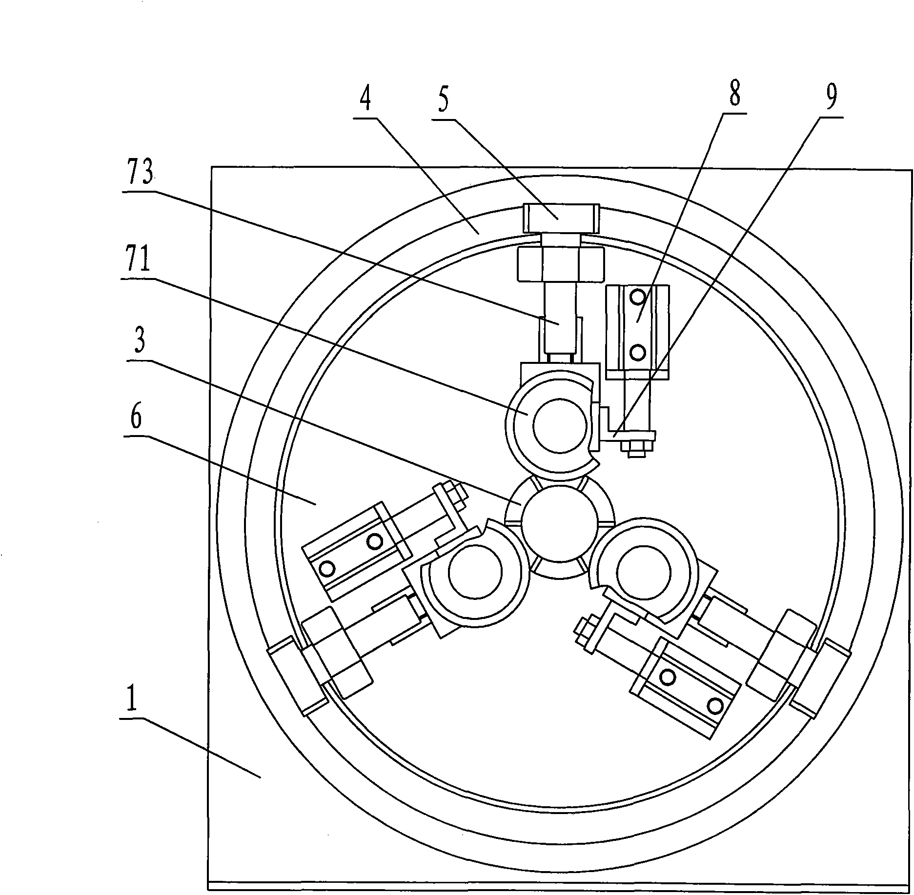
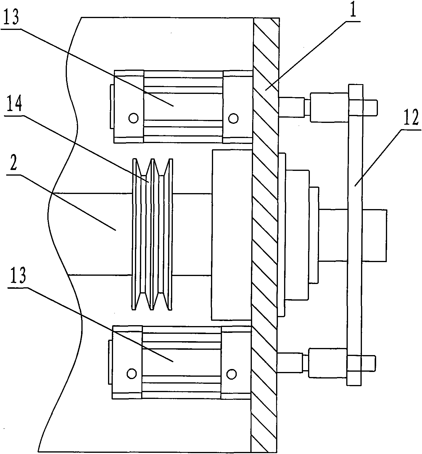
[0017] Such as Figure 1 to Figure 4 A fully automatic pipe cutting machine shown has a frame 1 and a main shaft 2, the main shaft 2 is driven to rotate by a motor through a belt drive 14, the main shaft 2 has a through hole, and a spacer 10 is fixed on the frame 1, and the spacer 10 is located on the The through hole of the main shaft 2 can be moved axially, and the inner hole of the spacer 10 is provided with a pull tube 11, and one end of the workpiece clamp 3 for telescopic clamping or loosening of the pipe extends into the inner hole of the spacer 10 One end of the pull tube 11 is threadedly connected, the other end of the pull tube 11 is...


PUM


Abstract

The invention discloses a full-automatic pipe cutting machine which comprises a frame, a rotary main shaft and a workpiece jacket, wherein, the workpiece jacket is positioned at the center of the front end of the main shaft and can telescopically clamp or loosen pipes; a large bevel gear is fixed on the front end surface of the frame, and the large bevel gear is meshed with a small bevel gear in a transmission manner; a turntable is fixed on the front end of the main shaft, and at least three cutting devices which can radially slide along the turntable are uniformly distributed on the circumference of the turntable; the small bevel gear is connected with the cutting devices in a transmission manner; the cutting devices comprise cutting blades; and when the main shaft drives the cutting devices to circumferentially rotate through the turntable, the small bevel gear is meshed with the large bevel gear in a transmission manner to drive the cutting blades to rotate. In the invention, by means of combination of high-speed autorotation and revolution of the cutting blades and radial movement along the pipes, the full-automatic pipe cutting machine cuts the pipes and makes an angled surface at cut positions to ensure bright, clear and tidy cross section of the pipes and improve machining precision; and a plurality of groups of the cutting blades can be employed simultaneously for machining the pipes, thus being beneficial to prolonging service life of the cutting blades and improving machining efficiency.

Description

technical field [0001] The invention relates to the technical field of pipe processing, in particular to a fully automatic pipe cutting machine. Background technique [0002] Pipes are used in various production and manufacturing fields. Most of the equipment used to cut pipes in the past is in the form of a single cutting piece, which cuts the pipe through the rotation of the cutting piece. This processing method has low cutting accuracy, slow cutting speed and high labor intensity. , It is also not conducive to environmental protection, so a processing method that uses multiple cutting blades arranged radially to cut the pipe at the same time appeared. When cutting, the position of the cutting blade relative to the pipe is fixed, and the cutting blade rotates. The cutting piece moves radially to cut the pipe. Although this cutting method improves the work efficiency and reduces the labor intensity, the section of the cut pipe is relatively rough, and burrs are easy to form...

Claims


Application Information

Patent Timeline
IPC IPC(8): B23D21/04
Inventor 周志玉林鹅俊吴宝坤吴叶峰
Owner 周志玉
Learn More