Metal-bar peeler

A metal bar and peeling machine technology, which is applied in the direction of metal processing machinery parts, metal processing, metal processing equipment, etc., can solve the problems of reducing labor intensity of employees, small size, and high labor intensity, so as to improve automatic control performance and reasonable design , the effect of convenient operation

Active Publication Date: 2012-02-29
TAIZHOU JINGHUA ENVIRONMENTAL PROTECTION EQUIP
View PDF2 Cites 1 Cited by
  • Summary
  • Abstract
  • Description
  • Claims
  • Application Information

AI Technical Summary

Problems solved by technology

The traditional peeling machine has the following problems in the work: 1. In order to make the front end of the metal rod blank pass through the peeling die so that the traction mechanism can be connected with the metal rod, the front end of the metal rod blank must be stripped in advance; Although the Chinese patent literature once disclosed a metal bar automatic stripping machine [Chinese Patent No.: ZL200810061562.1; authorized announcement number: C N101269424A] which can complete the stripping of the front end of the metal bar blank.
2. Although the above-mentioned head stripping machine has improved the speed of the head stripping process, there are also some problems in the head stripping process: a. The process of the head stripping process itself is complicated, the labor intensity is high, and the processing is inconvenient; b. The size of the processed metal rods is smaller than the size of the finished product, resulting in a lot of waste of raw materials
3. Workers must manually feed metal rods (such as copper rods) into the peeling mold for loading materials. Due to the long length and heavy weight of metal rods, there is a problem of high labor intensity for workers.
4. In the process of processing, there are still images with large noise and low safety factor
This semi-automatic metal bar peeling machine can automatically pass the metal bar head out of the peeling die hole and automatically send the stretched and peeled metal bar out of the frame, thus effectively reducing the labor intensity of employees , but there is still the problem that the front end of the metal rod blank needs to be stripped in advance

Method used


Image

  • Metal-bar peeler
  • Metal-bar peeler
  • Metal-bar peeler

Examples


Embodiment 1

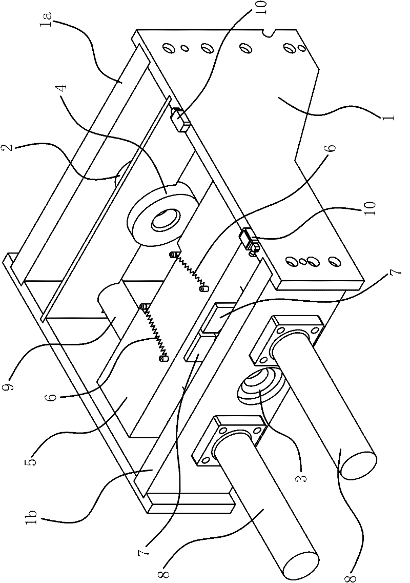
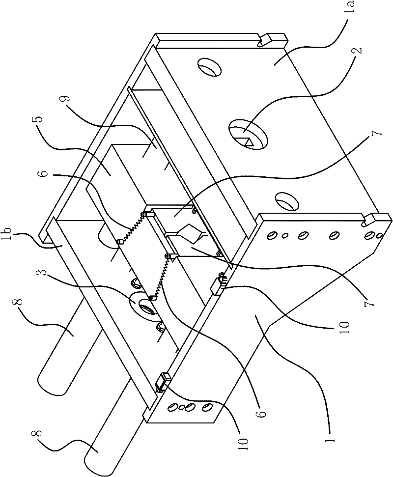
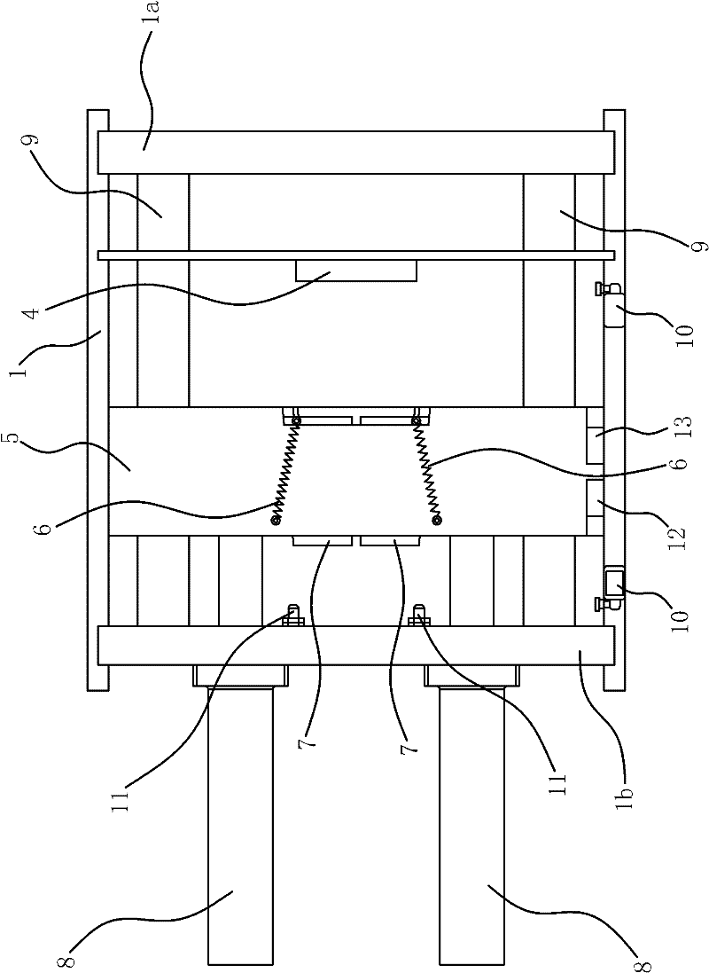
[0034] Such as Figure 1 to Figure 6 Shown, the peeling machine of this metal rod comprises frame 1, peeling die 2, guide member 3, connecting seat 5, power member 8, traction mechanism, clamping mechanism.

[0035] Specifically, there is a fixed seat-1a for fixing the peeling die 2 on the frame 1, and the peeling die 2 is fixed on the fixed seat-1a by bolts, so that the peeling die 2 can The mold corresponding to size selection is fixed on the holder-1a. Obviously, the frame 1 on one side of the peeling die 2 is a feed section, and the frame 1 on the other side of the peeling die 2 is a discharge portion. Frame 1 Frame 1 feeding part is provided with fixing seat 2 1b for fixing guide 3, and guide 3 is fixed on the fixing seat 2 1b by bolt, and the guide hole of round hole is arranged on this guide 3, and guide hole The center line of the center line and the center line of the peeling die 2 die holes are on the same straight line. Therefore, the guide member 3 can also sele...

Embodiment 2

[0049] Such as Figure 7 As shown, the structure and principle of this embodiment are basically the same as those of Embodiment 1, the difference lies in: a cylinder 14 capable of driving the corresponding chuck body 7 to move is provided between each chuck body 7 and the connecting seat 5, The cylinder body of the air cylinder 14 is hinged on the connecting body, and the piston rod is hinged on the corresponding chuck body 7 . Obviously, the hydraulic cylinder can replace the air cylinder 14 in this structure. When the cylinder 14 was in the extended state, the two chuck bodies 7 were in an expanded state, that is, the metal rod could be loosened; when the cylinder 14 was in the retracted state, the two chuck bodies 7 were in a tightened state, that is, the Clamp the metal rod.


PUM


Abstract

The invention provides a metal-bar peeler, belonging to the machine tool technical field. The metal-bar peeler solves the problem that before a metal bar is processed by the existing metal-bar peeler, the front end of a metal bar blank needs to be subjected to head peeling in advance, and then the metal bar can be processed. The metal-bar peeler comprises a rack, a peeling mould and a traction mechanism, wherein, the peeling mould and the traction mechanism are fixed on the rack; a connecting seat which can move along the rack feeding part is arranged on the rack feeding part; a power component which can drive the connecting seat to move is arranged on the rack; a material clamping mechanism which can clamp and loose a metal bar is arranged on the connecting seat; when the power componentdrives the connecting seat to move towards the peeling mould, the metal bar is clamped by the material clamping mechanism, and the head of the metal bar can penetrate the peeling mould to peel the head of the metal bar. The metal-bar peeler can satisfy workpieces which are not subjected to head peeling process in advance, thus having the advantage of improving the production efficiency of metal bars and the utilization rate of metal bar blanks, and having simple structure and reasonable design.

Description

technical field [0001] The invention belongs to the technical field of machine tools, and relates to a broaching machine tool, in particular to a metal bar peeling machine. Background technique [0002] Metal rod is an important raw material for the production of spare parts. In the production process, it generally needs to be cast and hot-pressed first. At this time, the shape of the blank obtained is irregular and the size does not meet the tolerance requirements. It is necessary to use a peeling machine for peeling operations. The surface of the embryo is removed to meet the requirements of the finished product. [0003] The peeling machine of traditional metal bar comprises frame and is fixed on the peeling mold on frame, and the frame of described peeling mold one side is feed section, and the frame of peeling mold other side is discharge section; A guide is provided on the feeding part of the frame, and a traction mechanism that can be connected with the head of the m...

Claims


Application Information

Patent Timeline
Patent Type & Authority Patents(China)
IPC IPC(8): B23D79/12B23Q3/06B23Q7/00
Inventor 邵英君
Owner TAIZHOU JINGHUA ENVIRONMENTAL PROTECTION EQUIP
Why Eureka
Try Eureka