Ontract replaceable joint of large space service robot
A service robot and joint technology, which is applied in the direction of manipulators, manufacturing tools, joints, etc., can solve the problems of small robot load to weight ratio, poor control accuracy, and large joint quality, and achieve light weight, improved position accuracy, and improved control accuracy. Effect
- Summary
- Abstract
- Description
- Claims
- Application Information
AI Technical Summary
Problems solved by technology
Method used
Image
Examples
specific Embodiment approach 1
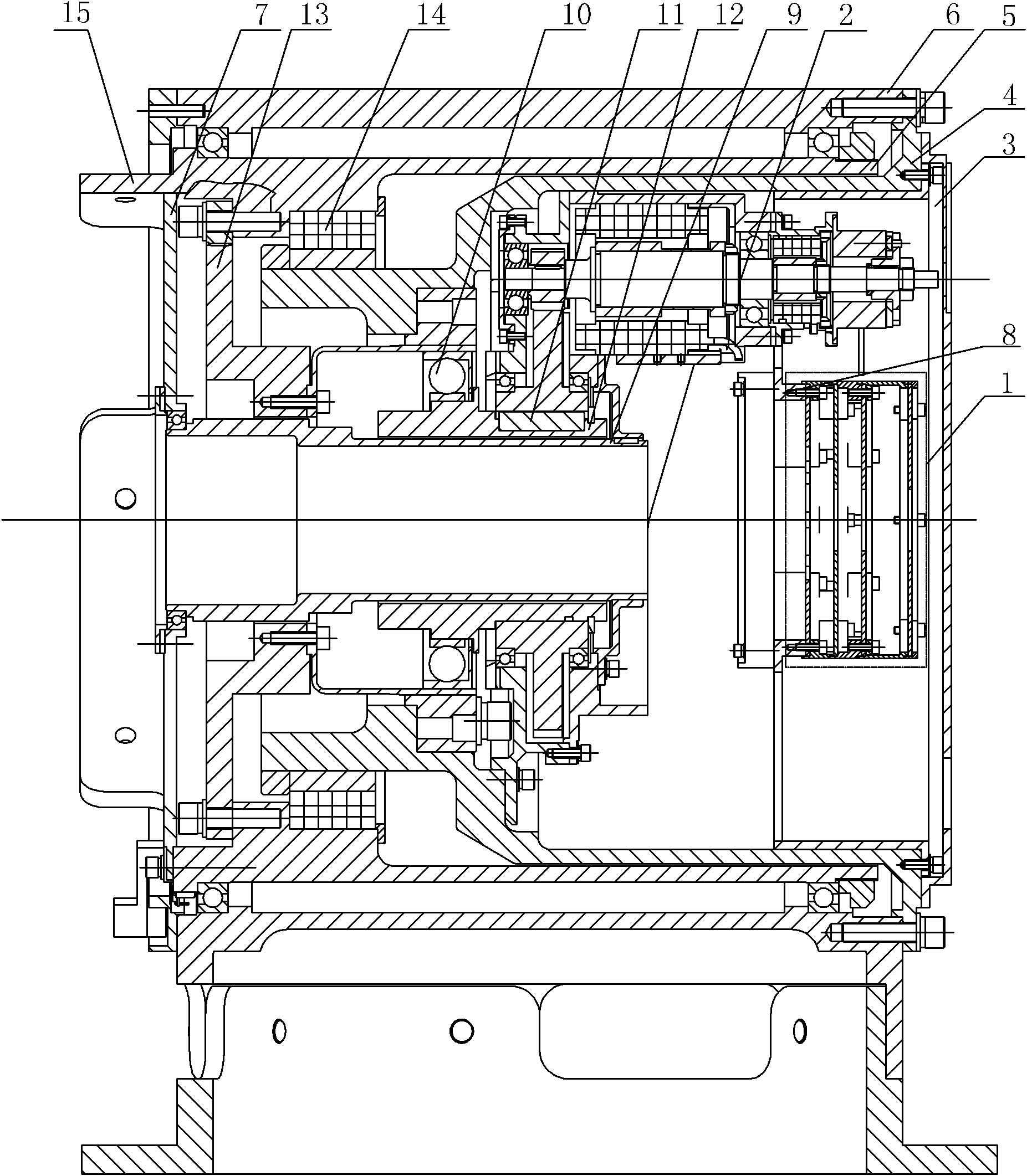
[0009] Specific implementation mode one: combine Figure 1-Figure 3 Describe this embodiment. The joint of this embodiment includes an electrical device 1, a drive device 2, a joint front cover 3, a joint inner shell 4, a joint output shell 5, a joint shell 6, a joint rear cover 7, a circuit board connector 8, a cylinder Shaped hollow shell 9, harmonic reducer 10, key 11, hollow shaft 12, torque sensor 13 and axial flange 15, the joint front cover 3 is installed on the joint inner shell 4, and the two are detachably connected, the joint inside The tail of the shell 4 is processed with an axial flange 15, the joint inner shell 4 is set in the joint shell 6, and the two are detachably connected, the joint output shell 5 is set between the joint inner shell 4 and the joint shell 6, and the joint output The shell 5 is rotatably connected to the joint shell 6, the joint back cover 7 is installed in the joint output shell 5, and the two are detachably connected, and the inner hole o...
specific Embodiment approach 2
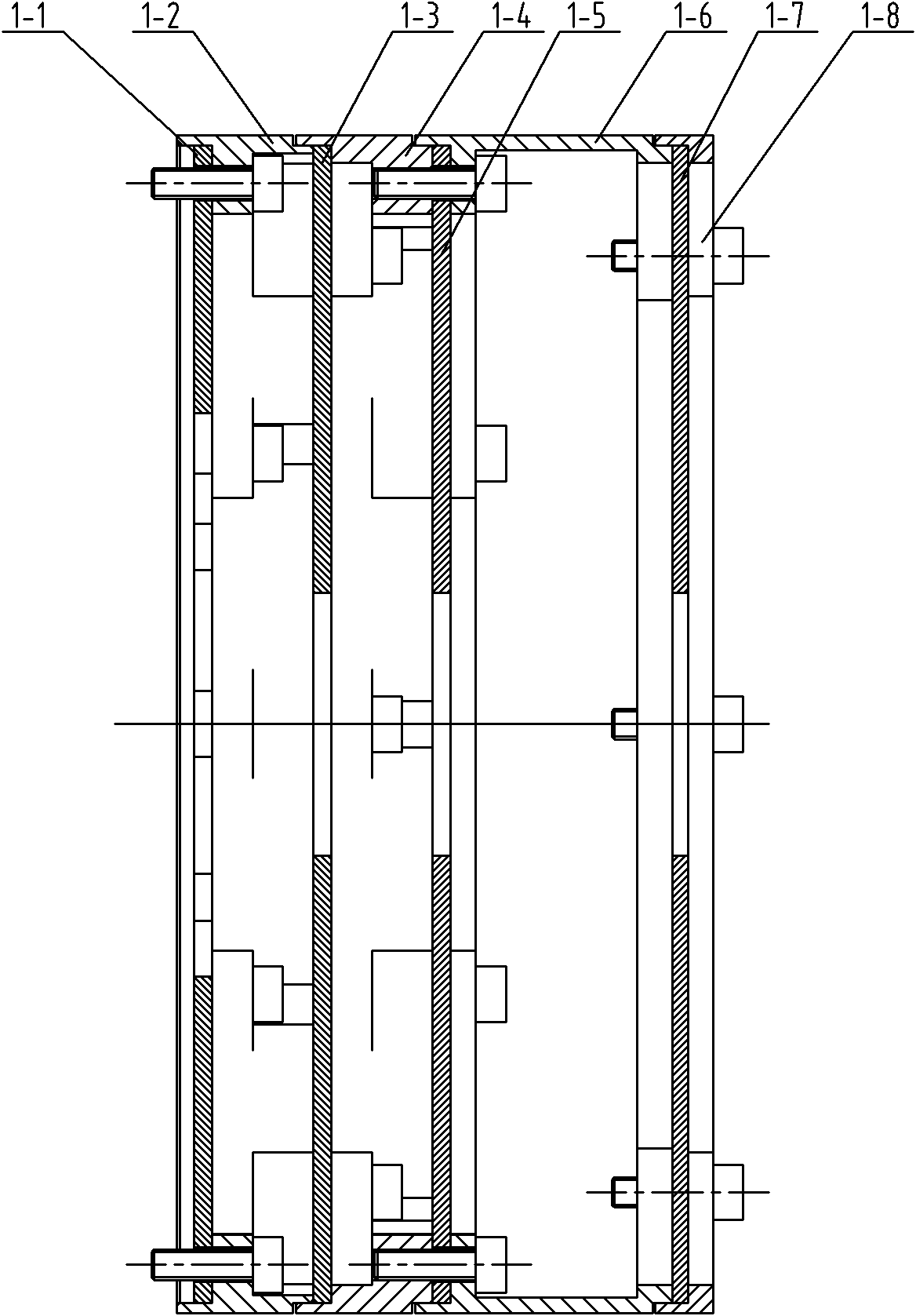
[0011] Specific implementation mode two: combination image 3 Describe this embodiment, the electrical device 1 of this embodiment consists of a joint driving circuit board 1-1, a first bracket 1-2, a joint control circuit board 1-3, a second bracket 1-4, and a joint power supply circuit board 1-5 The third bracket 1-6, the joint interface circuit board 1-7 and the joint interface circuit board pressure ring 1-8 are composed, the joint drive circuit board 1-1 is fixed on the circuit board connector 8 through the first bracket 1-2, and the joint The control circuit board 1-3 is fixed on the joint control circuit board support 1-2 through the second support 1-4, and the joint power circuit board 1-5 is fixed on the joint power circuit board support 1-4 through the third support 1-6 , the joint interface circuit board 1-7 is fixed on the joint interface circuit board bracket 1-6 through the joint interface circuit board pressing ring 1-8, the joint driving circuit board 1-1, the ...
specific Embodiment approach 3
[0012] Specific implementation mode three: combination figure 1 Describe this embodiment, the joint of this embodiment further includes a second rotary transformer 14, the second rotary transformer 14 is installed in the joint casing 6, and the two are fixedly connected. The joint resolver 14 is used to obtain high-precision joint position information to ensure joint control precision. Other components and connections are the same as those in the first embodiment.
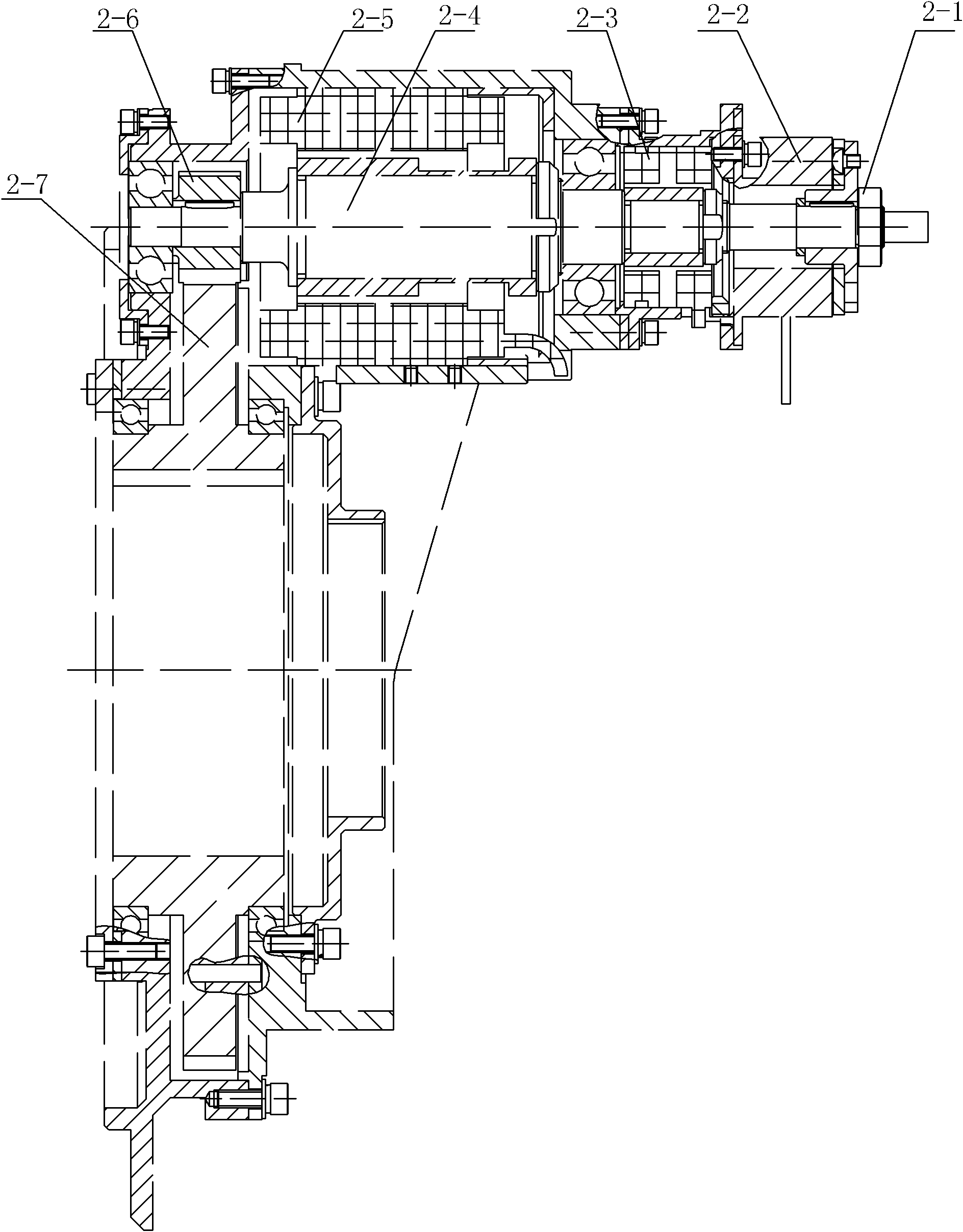
[0013] Working principle: The motor 2-5 is used as the power device of the entire joint, which converts electrical energy into mechanical energy and provides the joint with the required output power. The first rotary transformer 2-3 is used to detect the position of the rotor of the motor, and its existence is a prerequisite for high-precision servo control of the motor. At the same time, the holding brake 2-2 provides braking torque in emergency situations. The power of the joint is transmitted to the motor tra...
PUM
 Abstract
Description
Claims
Application Information
 - R&D
- Intellectual Property
- Life Sciences
- Materials
- Tech Scout
- Unparalleled Data Quality
- Higher Quality Content
- 60% Fewer Hallucinations
Browse by: Latest US Patents, China's latest patents, Technical Efficacy Thesaurus, Application Domain, Technology Topic, Popular Technical Reports.
© 2025 PatSnap. All rights reserved.Legal|Privacy policy|Modern Slavery Act Transparency Statement|Sitemap|About US| Contact US: help@patsnap.com


