Ontract replaceable joint of large space service robot

A technology for service robots and joints, applied in the directions of manipulators, manufacturing tools, joints, etc., can solve the problems of small load-to-weight ratio, large joint quality, and poor control accuracy of robots, and achieve light weight, improve control accuracy, and improve position accuracy. Effect

Inactive Publication Date: 2011-08-17
HARBIN INST OF TECH
View PDF0 Cites 0 Cited by
  • Summary
  • Abstract
  • Description
  • Claims
  • Application Information

AI Technical Summary

Problems solved by technology

[0004] The purpose of the present invention is to solve the problems of poor joint control accuracy of large-scale space service robots, the use of planetary gear transmission leads to large joint mass so that the robot’s load ratio is small, and the control circuit is installed outside the joints resulting in poor integration. A large-scale Space service robot joints

Method used


Image

  • Ontract replaceable joint of large space service robot
  • Ontract replaceable joint of large space service robot
  • Ontract replaceable joint of large space service robot

Examples


specific Embodiment approach 1

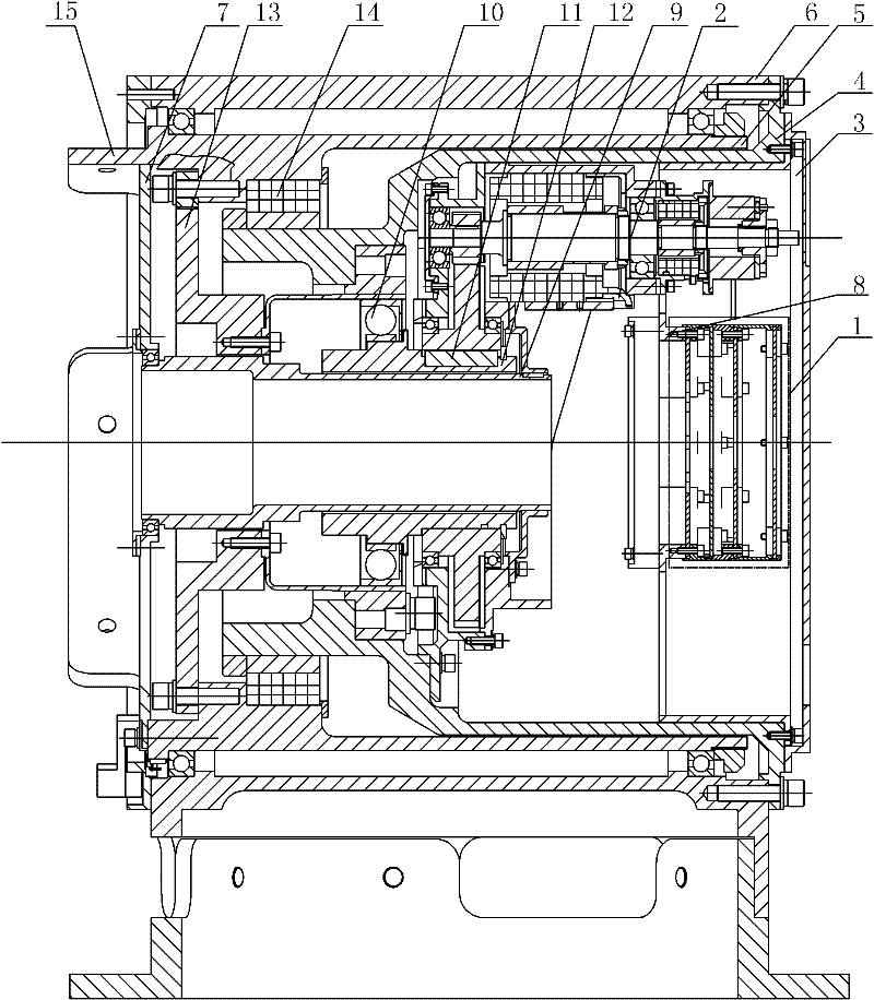
[0009] Specific implementation mode one: combine Figure 1-Figure 3 Describe this embodiment. The joint of this embodiment includes an electrical device 1, a drive device 2, a joint front cover 3, a joint inner shell 4, a joint output shell 5, a joint shell 6, a joint rear cover 7, a circuit board connector 8, a cylinder Shaped hollow shell 9, harmonic reducer 10, key 11, hollow shaft 12, torque sensor 13 and axial flange 15, the joint front cover 3 is installed on the joint inner shell 4, and the two are detachably connected, the joint inside The tail of the shell 4 is processed with an axial flange 15, the joint inner shell 4 is set in the joint shell 6, and the two are detachably connected, the joint output shell 5 is set between the joint inner shell 4 and the joint shell 6, and the joint output The shell 5 is rotatably connected to the joint shell 6, the joint back cover 7 is installed in the joint output shell 5, and the two are detachably connected, and the inner hole o...

specific Embodiment approach 2

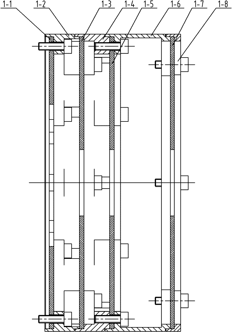
[0011] Specific implementation mode two: combination image 3 Describe this embodiment, the electrical device 1 of this embodiment consists of a joint driving circuit board 1-1, a first bracket 1-2, a joint control circuit board 1-3, a second bracket 1-4, and a joint power supply circuit board 1-5 The third bracket 1-6, the joint interface circuit board 1-7 and the joint interface circuit board pressure ring 1-8 are composed, the joint drive circuit board 1-1 is fixed on the circuit board connector 8 through the first bracket 1-2, and the joint The control circuit board 1-3 is fixed on the joint control circuit board support 1-2 through the second support 1-4, and the joint power circuit board 1-5 is fixed on the joint power circuit board support 1-4 through the third support 1-6 , the joint interface circuit board 1-7 is fixed on the joint interface circuit board bracket 1-6 through the joint interface circuit board pressing ring 1-8, the joint driving circuit board 1-1, the ...

specific Embodiment approach 3

[0012] Specific implementation mode three: combination figure 1 Describe this embodiment, the joint of this embodiment further includes a second rotary transformer 14, the second rotary transformer 14 is installed in the joint casing 6, and the two are fixedly connected. The joint resolver 14 is used to obtain high-precision joint position information to ensure joint control precision. Other components and connections are the same as those in the first embodiment.

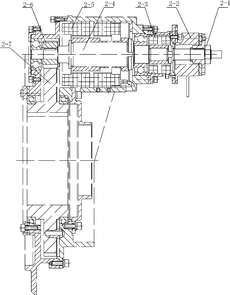
[0013] Working principle: The motor 2-5 is used as the power device of the entire joint, which converts electrical energy into mechanical energy and provides the joint with the required output power. The first rotary transformer 2-3 is used to detect the position of the rotor of the motor, and its existence is a prerequisite for high-precision servo control of the motor. At the same time, the holding brake 2-2 provides braking torque in emergency situations. The power of the joint is transmitted to the motor tra...


PUM


Abstract

The invention relates to an ontract replaceable joint of a large space service robot, in particular to a robot joint, which aims to solve the problems of poor joint control accuracy, large joint mass caused by using planetary gear transmission, small load self-weight ratio for a robot, and poor integration caused by arranging a control circuit outside a joint of the traditional large space service robot. The output end of a transmission shaft for a motor is connected with a pinion in a transmission way; the pinion is engaged with a bull gear; the bull gear is connected with a hollow shaft through a key in a transmission way; the hollow shaft is integrated with a harmonic speed reducer; a cylindrical hollow shell is arranged inside the hollow shaft; the tail of the cylindrical hollow shellis connected with a back cap of the joint; the harmonic speed reducer is connected with the small diameter end of a torque transducer which is arranged inside the output shell of the joint and is sleeved outside the cylindrical hollow shell; and the large diameter end of the torque transducer is connected with the output shell of the joint in a dismountable way. The invention is used for large space service robots.

Description

technical field [0001] The invention relates to a robot joint. Background technique [0002] According to the current situation of the development of space technology in our country, it has become a trend to build our own space station. Although some progress has been made in the field of space robots in China, the application field belongs to small space maintenance robots, and its design features cannot be applied to large output torque output and long-life operations. At present, there are no large-scale robots in China that specialize in the construction, maintenance, and capture of space stations and large-scale space objects, and can help astronauts go out of the cabin for space operations. A large-scale space robot that can realize the above functions has become a key link in my country's further exploration of space. Joints and their control devices are important components of space robots. The performance of joints directly determines the load-to-weight ratio, end...

Claims


Application Information

Patent Timeline
Patent Type & Authority Patents(China)
IPC IPC(8): B25J17/00B25J13/00B25J19/00
Inventor 孙敬颋史士财陈泓刘宏
Owner HARBIN INST OF TECH
Why Eureka
Try Eureka