
Reciprocating type hydrodynamic force water drawing rotating machinery power converting machine

A rotating machinery and hydrodynamic technology, which is applied in the field of reciprocating hydrodynamic pumping and rotating machinery power converters, can solve problems such as large waste of water energy, and achieve the effects of low layout requirements, low water flow requirements, and environmental friendliness.

Active Publication Date: 2010-12-15
王少林
View PDF4 Cites 5 Cited by
  • Summary
  • Abstract
  • Description
  • Claims
  • Application Information

AI Technical Summary

Problems solved by technology

[0002] Existing water energy machines mostly use impeller-type "water turbines" to convert water flow into torque power generation, but "water turbines" have strict requirements on the size of water head and water flow. During the conversion process, the water energy of high-speed passing water flow is relatively large Large, and the damage to the water resources and environment is also relatively large

Method used


Image

  • Reciprocating type hydrodynamic force water drawing rotating machinery power converting machine
  • Reciprocating type hydrodynamic force water drawing rotating machinery power converting machine
  • Reciprocating type hydrodynamic force water drawing rotating machinery power converting machine

Examples


Embodiment Construction

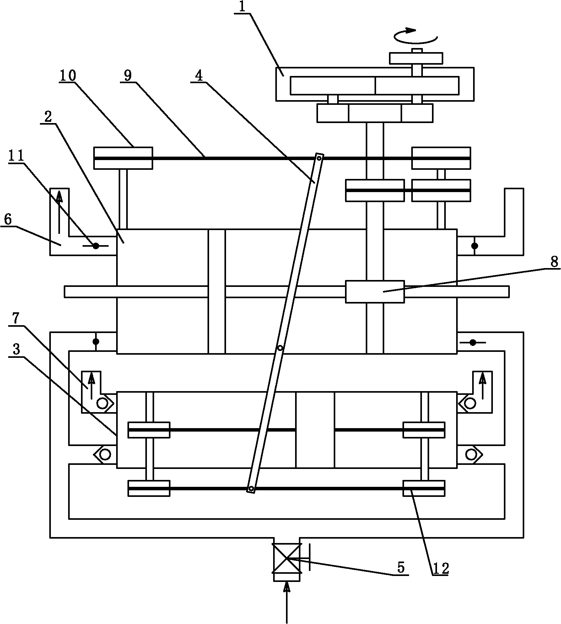
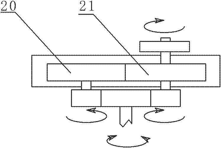
[0014] Such as figure 1 In, a reciprocating hydrodynamic pumping rotary mechanical power conversion machine, the piston rod of the driving cylinder 2 is connected to the conversion device 1 through the rack and pinion mechanism 8; in the conversion device 1, the reverse transmission wheel 20 and the forward transmission The wheel 21 is connected, and the reverse transmission wheel 20 and the forward transmission wheel 21 are provided with a ratchet mechanism in the opposite direction. Such as image 3 In the rack and pinion mechanism 8, the shaft is connected to the reverse transmission wheel 20 and the forward transmission wheel 21 at the same time, and the reverse transmission wheel 20 and the forward transmission wheel 21 are also connected to each other. Due to the built-in ratchet mechanism, the input The torque of the reciprocating rotation is converted into the torque of one direction rotation. Specifically, when the input is counterclockwise rotation, the forward trans...


PUM


Abstract

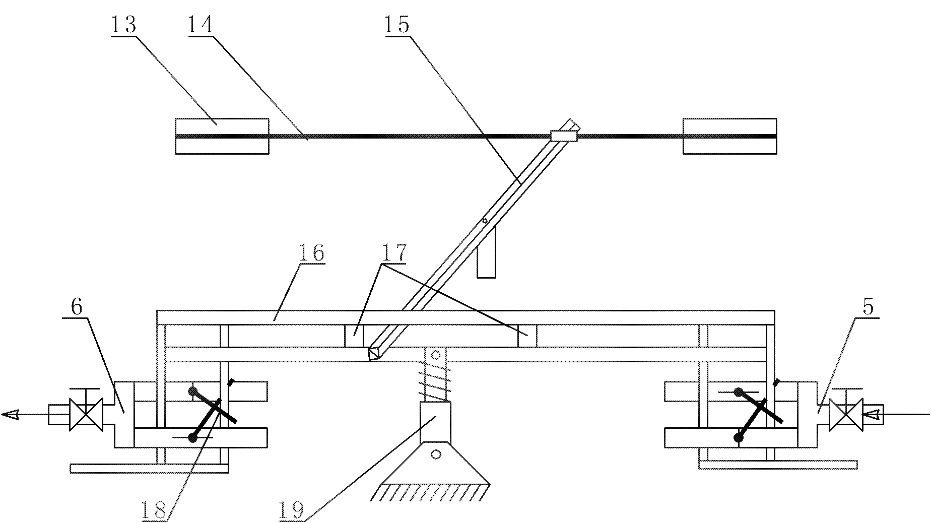
The invention relates to a reciprocating type hydrodynamic force water drawing rotating machinery power converting machine. The piston rod of a driving cylinder is connected with a converting device by virtue of a gear rack mechanism; the two ends of the driving cylinder are respectively provided with two reversing valves which are inverse in on-off state, the reversing valve is connected with a reversing valve mechanism; the gear rack mechanism is also connected with a chain transmission mechanism, the lever transmission chain in the chain transmission mechanism is connected with one end of a lever transmission mechanism, the other end is connected with a water drawing machine chain transmission mechanism,the water drawing machine chain transmission mechanism is connected with the piston rod of a water drawing cylinder, and the two ends of the water drawing cylinder are respectively provided with two one-way valves which are inverse in direction. The equipment of the invention mainly utilizes potential energy of water, pressure difference produced by water level difference is utilized to push the piston of the driving cylinder, thus having low requirement on water flow, requiring no dam and having less environmental impact. The equipment is in full mechanical mode, has low arrangement requirement, is environmentally friendly and is applicable to being used at the position where water flow is within certain head drop.

Description

Technical field [0001] The invention relates to a hydraulic machine, in particular to a reciprocating hydraulic pumping rotary mechanical power conversion machine that can pump water to a higher level than the original water flow by adopting a piston method and output torque at the same time. Background technique [0002] Existing hydraulic turbines mostly use impeller-type "water turbines" to convert water flow into torque to generate electricity. However, "water turbines" have strict requirements on the size of the water head and water flow. During the conversion process, the water energy of the high-speed water flow is more wasteful. Large, and the damage to the water environment by dam construction is also great. Summary of the invention [0003] The technical problem to be solved by the present invention is to provide a reciprocating hydrodynamic pumping rotary mechanical power conversion machine, which can reduce the dependence of hydropower development on the dam, has low w...

Claims


Application Information

Patent Timeline
Patent Type & Authority Applications(China)
IPC IPC(8): F03B13/06
CPCY02E60/17Y02E10/22Y02E10/20Y02E60/16
Inventor 王少林
Owner 王少林
Learn More