Constrained speed reducer with small teeth difference

A technology with less tooth difference and reducer, which is applied in the direction of gear transmission, belt/chain/gear, transmission, etc., to achieve large load transmission capacity, simple and compact structure, and improve transmission efficiency

Inactive Publication Date: 2010-12-15
CHONGQING UNIV
View PDF6 Cites 9 Cited by
  • Summary
  • Abstract
  • Description
  • Claims
  • Application Information

AI Technical Summary

Problems solved by technology

Contents of the invention

Method used


Image

  • Constrained speed reducer with small teeth difference
  • Constrained speed reducer with small teeth difference
  • Constrained speed reducer with small teeth difference

Examples


Embodiment Construction

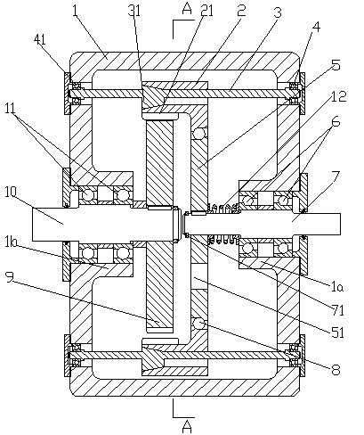
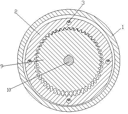
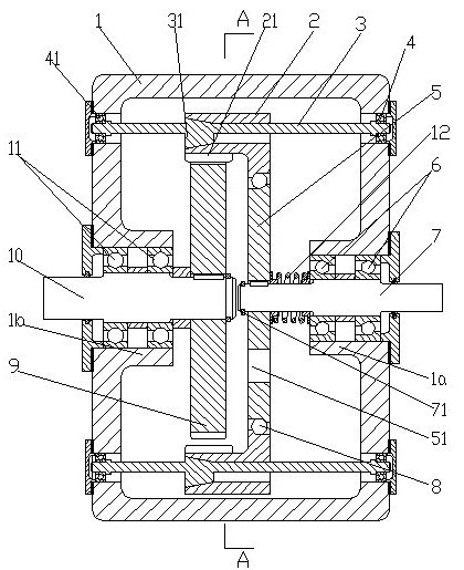
[0019] figure 1 It is a structural schematic diagram of the present invention, figure 2 for figure 1 View along the A-A direction, as shown in the figure: the constrained small-tooth-difference reducer of this embodiment includes a housing 1, a power input shaft 7 and a power output shaft 10, and the power input shaft 7 is fixedly arranged with an eccentric in the circumferential direction. Sleeve 5, said eccentric sleeve 5 rotates on the outer circle and is equipped with a transmission inner gear plate 2 with internal meshing teeth 21, and said power output shaft 10 is fixedly fitted with an external gear 9 in the circumferential direction, said external gear 9 and the transmission inner gear The internal meshing teeth 21 of the tooth disc 2 are meshed with less tooth difference;

[0020] The constraining shaft 3 parallel to the power input shaft 7 and having an eccentric shaft section 31 is set in rotational cooperation with the housing 1, and the eccentric shaft segment ...


PUM


Abstract

The invention discloses a constrained speed reducer with small teeth difference, which comprises a shell, a power input shaft and a power output shaft, wherein the power input shaft is provided with a transmission inner tooth disc of inner engaging teeth through an eccentric sleeve, the power output shaft is fixedly matched and provided with an outer gear in the circumferential direction, and the outer gear is engaged with the inner engaging teeth of the transmission inner tooth disc in a small teeth difference mode; and eccentric shaft sections of constraint shafts in running fit with the shell pass through the transmission inner tooth disc and are in running fit with the transmission inner tooth disc, at least two constraint shafts are uniformly distributed along the circumferential direction, and the eccentric distance of the eccentric shaft sections is equal to that of the eccentric sleeve. The constrained speed reducer eliminates the relative spinning motion of a power input mechanism, outputs power by revolution, and has high reduction ratio, high transmission rigidity and high load transfer capability; when motion disturbance or other additional motion appears, the speed reducer can rotate normally, improve the transmission efficiency and successfully output the motion; meanwhile, the speed reducer has a simple and compact structure and small volume mass, and provides an effective path for selection of the speed reducer in mechanical engineering.

Description

technical field [0001] The invention relates to a speed reducer, in particular to a speed reducer with high precision and small tooth difference. Background technique [0002] The reducer is a device that reduces the high speed of the power machine to the speed suitable for the working machine, and is widely used in the equipment industry. With the development of the equipment industry, higher requirements are put forward for the reducer. The multi-stage gear reducer is widely used in the prior art. The multi-stage gear reducer uses multiple sets of gear meshing pairs to fit the transmission ratio. When the reduction ratio is required to be slightly larger, its structure is complicated and the volume is also large; The gear reducer can obtain a large reduction ratio, but it needs to arrange multiple sets of gears and gear shafts in the radial direction, the structure is relatively complicated, and the structural arrangement is difficult and the volume is large. In order to...

Claims


Application Information

Patent Timeline
Patent Type & Authority Applications(China)
IPC IPC(8): F16H1/32
Inventor 杨为陆国栋
Owner CHONGQING UNIV
Why Eureka
Try Eureka