Crankshaft magnetic detector
A crankshaft and magnetic detection technology, applied in the direction of material magnetic variables, can solve the problems of non-conduction, questionable effect, easy deformation, etc., and achieve the effects of uniform magnetic field, safe and reliable failure rate, and sufficient magnetization
- Summary
- Abstract
- Description
- Claims
- Application Information
AI Technical Summary
Problems solved by technology
Method used
Image
Examples
Embodiment
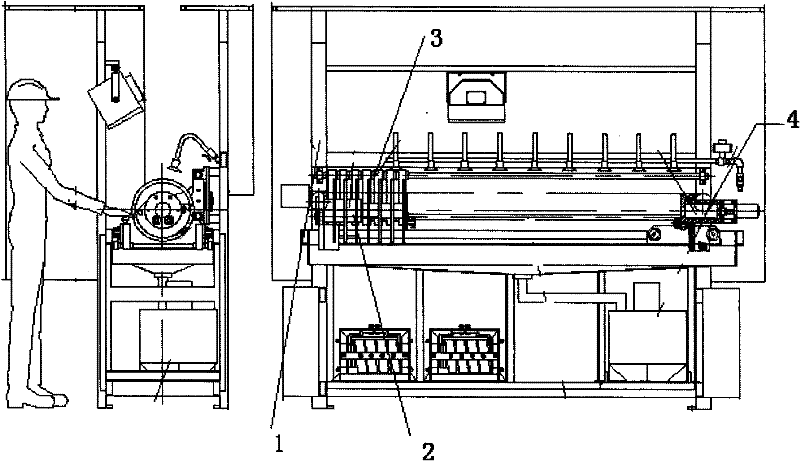
[0024] Such as figure 1 As shown, the main body of a crankshaft magnetic detector provided by the present invention is provided with a clamping energized circumferential magnetization device consisting of headstock 2 and tailstock 4 chucks on the guide rail of the frame assembly 1 of the fuselage , the base of the 2 chucks of the left headstock is fixed, and the position of the 4 chucks of the right tailstock can be moved and locked according to the length of the crankshaft. A cylinder for clamping the crankshaft is installed behind the chucks of the tailstock. The chuck conductive plate 17 that is energized after the crankshaft is clamped is all provided on the axle. An electric control box and an equipment air control box are respectively arranged on the left and right sides of the frame assembly. A multi-turn longitudinal magnetizing coil 3 that can extend longitudinally is arranged between the chucks of the head and the tailstock, and a workpiece rotating device is arrang...
PUM
| Property | Measurement | Unit |
|---|---|---|
| length | aaaaa | aaaaa |
Abstract
Description
Claims
Application Information
 - R&D
- Intellectual Property
- Life Sciences
- Materials
- Tech Scout
- Unparalleled Data Quality
- Higher Quality Content
- 60% Fewer Hallucinations
Browse by: Latest US Patents, China's latest patents, Technical Efficacy Thesaurus, Application Domain, Technology Topic, Popular Technical Reports.
© 2025 PatSnap. All rights reserved.Legal|Privacy policy|Modern Slavery Act Transparency Statement|Sitemap|About US| Contact US: help@patsnap.com


