Method for processing ultrasonic emission delay

A technology of ultrasonic transmission and delay processing, which is applied in the field of delayed transmission of ultrasonic signals, can solve the problems of increasing system cost, multi-system resources, occupation, etc., and achieve the effect of reducing demand and improving system cost performance

Inactive Publication Date: 2010-12-15
SHENZHEN LANDWIND IND
View PDF3 Cites 12 Cited by
  • Summary
  • Abstract
  • Description
  • Claims
  • Application Information

AI Technical Summary

Problems solved by technology

[0008] The general ultrasonic transmission delay processing method, each transmission channel uses a delay counte...

Method used


Image

  • Method for processing ultrasonic emission delay
  • Method for processing ultrasonic emission delay
  • Method for processing ultrasonic emission delay

Examples


Embodiment Construction

[0035] Below according to accompanying drawing and embodiment the present invention will be described in further detail:

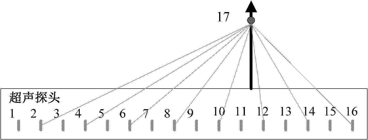
[0036] In the case of a certain system master clock, the relative delay parameter depends on the distance difference between the adjacent channel and the focal point. Divide this distance difference by the ultrasonic sound speed to get the delay time, and divide the delay time by one period of the master clock. The length of time, the value of the relative delay parameter is obtained.

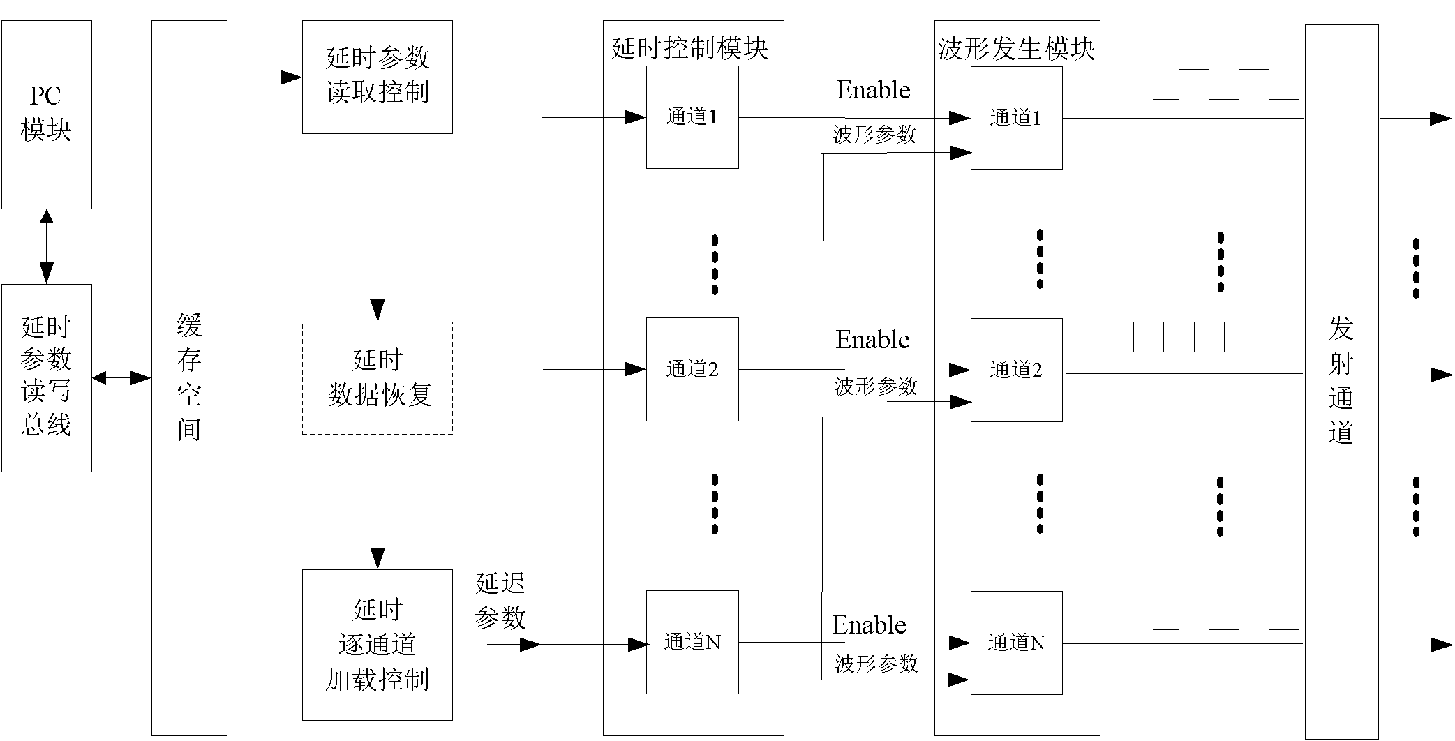
[0037] According to the above principle, if the minimum relative delay is greater than a certain value, the relative delay can be recoded, and a new relative delay value can be obtained by subtracting the minimum relative delay value from the relative delay value, which can make The relative delay parameter is smaller, and the delay value can be restored when the relative delay parameter is read, that is, the default minimum relative delay value is first added to obtain the...


PUM


Abstract

The invention provides a method for processing ultrasonic emission delay. Saved delay parameters are relative delay parameters, namely an earliest emission channel saves the delay relative to an emission starting signal, other channels save relative delay values with adjacent channels; or the delay values of adjacent channels are encoded so as to further reduce the bit width of the delay parameter; because the delay difference of adjacent channels is extremely small, generally only a space of less than 8 bits can save the delay; and thus the size of a cache for saving the delay can be reducedby more than half, a control unit for delay count is simplified, and the cost performance of the system is improved.

Description

technical field [0001] The invention provides a method for delay processing of ultrasonic transmission, in particular to a method for processing delayed transmission of ultrasonic signals for reducing the storage space occupied by ultrasonic transmission delay data. Background technique [0002] Such as figure 1 Shown: The ultrasound system consists of a probe, T / R switch, scan control, transmit channel (including delay control, waveform generation, waveform drive) and receive channel (reception and synthesis, signal processing, image processing and display). Among them, the probe is used for mutual conversion of electrical signals and acoustic signals, the T / R switch is used to isolate the transmission and reception channels, the transmission channel is used to generate and drive the transmission waveform, and the reception channel is used to receive echo signals and perform beamforming. Signal processing, image processing and display, etc., this technology is applied to t...

Claims


Application Information

Patent Timeline
IPC IPC(8): G01S7/52
Inventor 傅勇张羽
Owner SHENZHEN LANDWIND IND
Why Eureka
Try Eureka