Method and system for automatically switching master station-centralized spare power source

A self-switching and centralized technology for backup power supply, applied in electrical components, circuit devices, etc., can solve problems such as changes, inability to adapt to the operation mode, inability to solve complex systems, complex control, etc., to achieve the effect of improving reliability

Inactive Publication Date: 2010-12-15
ZHONGSHAN POWER SUPPLY BUREAU OF GUANGDONG POWER GRID
View PDF2 Cites 21 Cited by
  • Summary
  • Abstract
  • Description
  • Claims
  • Application Information

AI Technical Summary

Problems solved by technology

In the current standby and automatic switching mode, the problem of automatic input of backup power is usually solved based on local information, and each substation of the power system is installed to establish its own standby and automatic switching mode. For the main station of the power system In other words, it is impossible to know the switching status of each substation's backup and automatic switching, and it is impossible to perform remote control. There are certain decision-making limitations, and it cannot adapt to changes in operating modes, nor can it solve the problems of complex systems and complex controls. For example: remote backup Automatic power input, single power supply serial power supply, etc.
In addition, due to the limitation of information, the control strategy of local backup and automatic switching cannot realize the cooperation with the safety automatic control device, the optimal coordination between different backup and automatic switching, the cooperation with protection, and the overload control of backup power supply, etc. The reliability of power supply protection has limitations and cannot be applied to the long-term development of the power system

Method used


Image

  • Method and system for automatically switching master station-centralized spare power source
  • Method and system for automatically switching master station-centralized spare power source
  • Method and system for automatically switching master station-centralized spare power source

Examples


Embodiment Construction

[0023] In the following, the method for self-switching on the centralized backup power supply of the master station and the system for automatically turning on the centralized backup power supply of the master station according to the present invention will be described in detail in the form of specific embodiments.

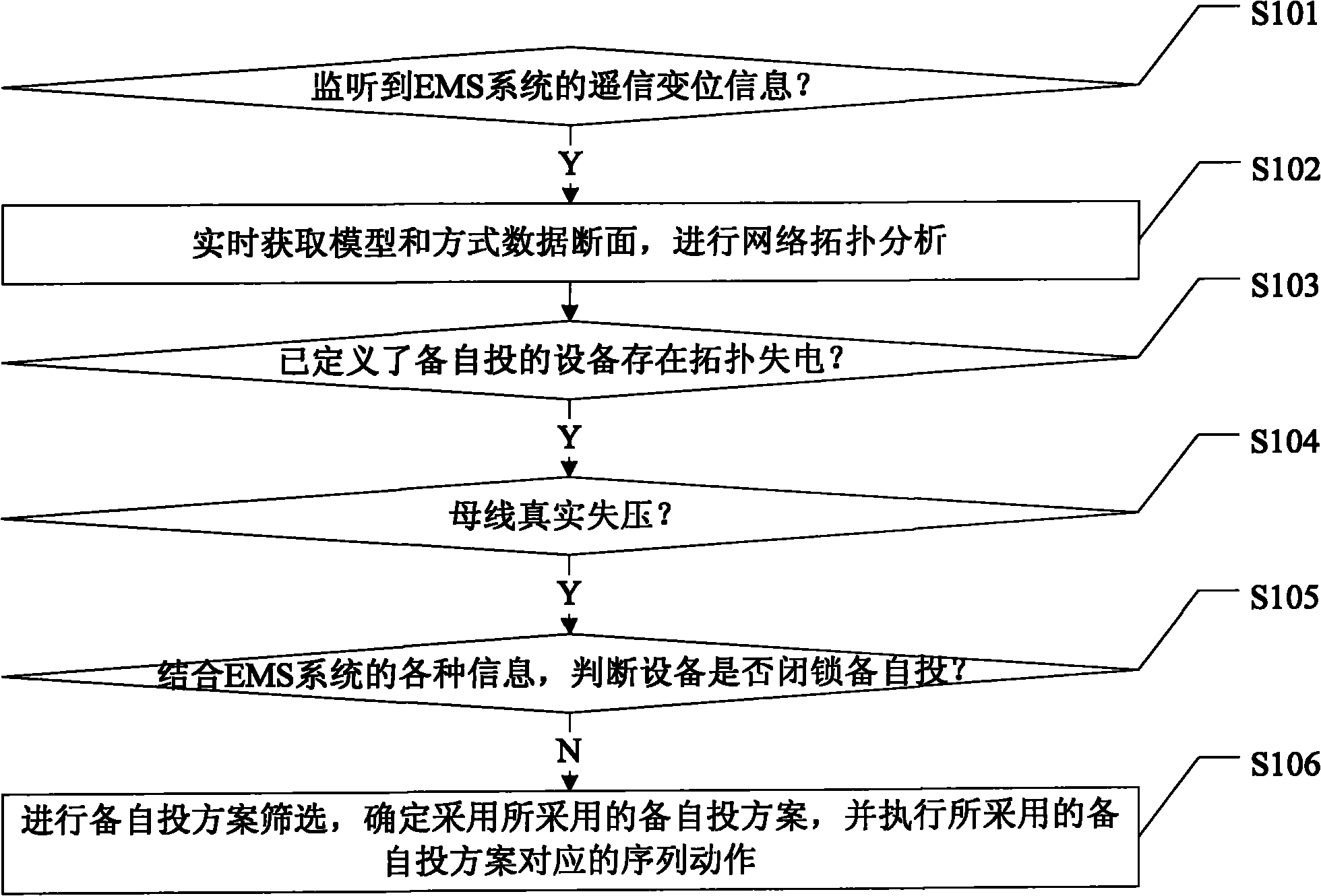
[0024] see figure 1 As shown, it is a schematic flow diagram of an embodiment of the self-switching method of the centralized backup power supply of the master station of the present invention, which includes steps:

[0025] Step S101: Monitor the remote signaling displacement information of the EMS system (Energy Management System), and judge whether the remote signaling displacement information of the EMS system is received, and if so, proceed to step S102;

[0026] Step S102: Obtain topology model information and mode data sections in real time, perform network topology analysis, and proceed to step S103 after the analysis is completed;

[0027] Step S103: Ac...


PUM


Abstract

The invention relates to a method and a system for automatically switching a master station-centralized spare power source. The method comprises the following steps of: monitoring remote signaling displacement information of an enhanced message service (EMS) system in real time; when the remote signaling displacement information is monitored, starting a spare power automatic switching analysis process to obtain topological model information and mode data cross section; analyzing a network topology; judging whether a bus truly loses voltage or not under the condition that the existence of topology power loss in spare power automatic switching equipment is defined by analysis; if the bus truly loses voltage, judging whether the equipment is locked for spare power automatic switching or not according to the information of the EMS system; and if the equipment is not locked for spare power automatic switching, determining an adopted spare power automatic switching scheme by screening to perform a sequence action corresponding to the spare power automatic switching scheme. Spare power automatic switching logic analysis is performed combined with the real-time information of the EMS system, so that power supply protection reliability is enhanced and long-term development of a power supply system is facilitated.

Description

technical field [0001] The invention relates to the field of automatic dispatching of electric power systems, in particular to a method for self-injection of a centralized backup power supply of a main station, and a system for automatic switching of a centralized backup power supply of a main station. Background technique [0002] With the development of social economy, the scale of the power grid is expanding day by day, the structure of the power grid is becoming more and more complex, and users have higher and higher requirements for the quality and reliability of power supply. In order to effectively ensure the reliability of power supply, a backup Switching mode, when the power supply fails, switch to the backup power supply to meet the user's demand for power supply reliability. In the current backup and automatic switching mode, the problem of automatic input of backup power is usually solved based on local information. It is to install and establish its own backup a...

Claims


Application Information

Patent Timeline
Patent Type & Authority Applications(China)
IPC IPC(8): H02J13/00
Inventor 陈波
Owner ZHONGSHAN POWER SUPPLY BUREAU OF GUANGDONG POWER GRID
Why Eureka
Try Eureka