
Method for controlling position-less sensor of switched reluctance motor

A technology of switched reluctance motor and control method, applied in electronic commutator, model/simulation of control purpose, etc., can solve the problems of high software and hardware resource occupancy rate, limited working area, complex algorithm, etc., to achieve universality Strong, great application prospects, simple algorithm effect

Inactive Publication Date: 2010-12-15
NANJING UNIV OF AERONAUTICS & ASTRONAUTICS
View PDF3 Cites 18 Cited by
  • Summary
  • Abstract
  • Description
  • Claims
  • Application Information

AI Technical Summary

Problems solved by technology

[0012] A position sensorless method that does not need to directly estimate the continuous position signal, but only needs to estimate the driving signals of each phase in real time, overcomes the problems of the traditional position sensorless method, such as complex algorithm, high software and hardware resource occupancy, and limited working area

Method used


Image

  • Method for controlling position-less sensor of switched reluctance motor
  • Method for controlling position-less sensor of switched reluctance motor
  • Method for controlling position-less sensor of switched reluctance motor

Examples


Embodiment Construction

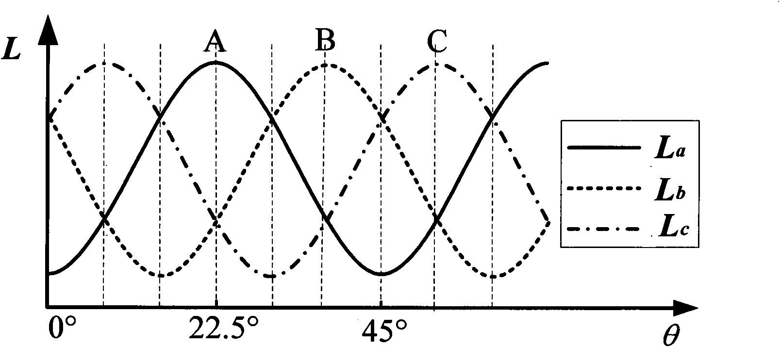
[0029] The invention compares the phase inductance calculation value of the conduction phase with the dynamic threshold value of the on / off angular position inductance to obtain the off signal of the current estimated phase and the on signal of the next on phase, and realizes the operation without position sensor.

[0030] Below in conjunction with accompanying drawing, the technical scheme of invention is described in detail:

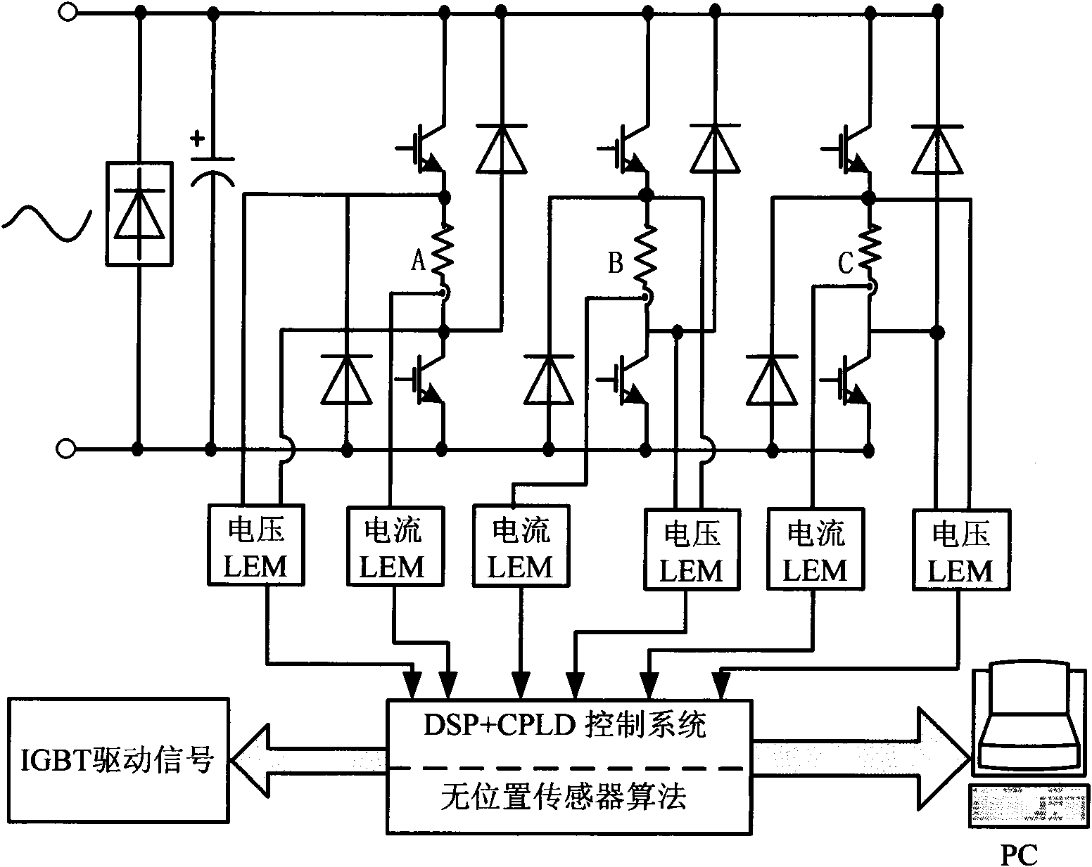
[0031] figure 1 A block diagram of a switched reluctance motor speed control system. The switched reluctance motor speed control system is mainly composed of a switched reluctance motor (SRM), a power converter, a control system (DSP+CPLD), a position sensor, and a voltage and current detection and protection circuit. Among them, the controller is the core of the system, which collects, calculates and processes the detection signal, completes the relevant control algorithm, and outputs the corresponding control signal. The inductance calculation and ...


PUM


Abstract

The invention discloses a method for controlling a position-less sensor of a switched reluctance motor, and belongs to the technical field of switched reluctance motor control. The method comprises the following steps of: based on the basic characteristic that the inductance of the switched reluctance motor is periodically changed along with a rotor position, establishing a precise inductance mathematical model according to an inductance characteristic curve, and setting an inductance threshold value of a turn-on / turn-off angular position by using the mathematical model; sampling current and end voltage of each phase, and calculating real-time inductance; and comparing the phase inductance calculation value of the current estimation phase with the inductance threshold value of the turn-off angular position of the phase and the inductance threshold value of the turn-on angular position of the next turn-on phase respectively to obtain a turn-off signal of the current estimation phase and a turn-on signal of the next turn-on phase so as to directly acquire a driving signal of each phase and realize the operation of the position-less sensor. The algorithm can realize turn-on / turn-off angle control by adopting a method for directly estimating the driving signal, meets the requirement of motor optimization control, and is simple and convenient to implement.

Description

technical field [0001] The invention relates to a position sensorless control method of a switched reluctance motor, which belongs to the technical field of switched reluctance motor control. technical background [0002] For the switched reluctance motor drive system, it is necessary to obtain the position information of the rotor in real time and accurately to ensure the reliable operation and high-performance control of the motor. At present, external photoelectric or magnetic sensitive equiaxial position detectors are generally used. Adding a mechanical position sensor increases the volume of the motor, increases the complexity of motor processing, greatly reduces the advantages of the simple structure of the switched reluctance motor, and reduces the reliability of the motor when it is working, increasing the cost. Therefore, it is of great research value to explore practical indirect position detection schemes. [0003] So far, scholars from various countries have do...

Claims


Application Information

Patent Timeline
IPC IPC(8): H02P6/18H02P6/34
Inventor 蔡骏邓智泉
Owner NANJING UNIV OF AERONAUTICS & ASTRONAUTICS
Learn More