Eureka AIR delivers breakthrough ideas for toughest innovation challenges, trusted by R&D personnel around the world.

Method and device for detecting lens in real time in fully automatic two-dimensional (2D) to three-dimensional (3D) technology

A lens detection, fully automatic technology, applied in the direction of television, electrical components, stereo systems, etc., can solve the problems of modes that do not conform to online processing, complex principles, multi-time, etc., to enhance robustness and adaptability, principle and Simple process and high real-time effect

Active Publication Date: 2010-12-15
TSINGHUA UNIV
View PDF5 Cites 11 Cited by
  • Summary
  • Abstract
  • Description
  • Claims
  • Application Information

AI Technical Summary

Problems solved by technology

For example, some methods have too high computational time complexity, they may need to convert the original image from RGB space to HSV or La * b * color space, or need to perform block matching for each sub-block of the image, or need to detect and compare the edge of the object in the image, so all in all, they will consume a lot of time when performing these processes, and cannot meet the full Real-time requirements of automatic 2D to 3D system
In addition, the principles used in some methods are too complicated and the steps are too cumbersome, which is not conducive to the realization of the hardware of this module in the future.
However, some clustering-based shot segmentation methods need to read the information of all frames first, and then classify these frames, which is not in line with the online processing of a fully automatic 2D to 3D system that reads a frame and judges a frame. model

Method used


Image

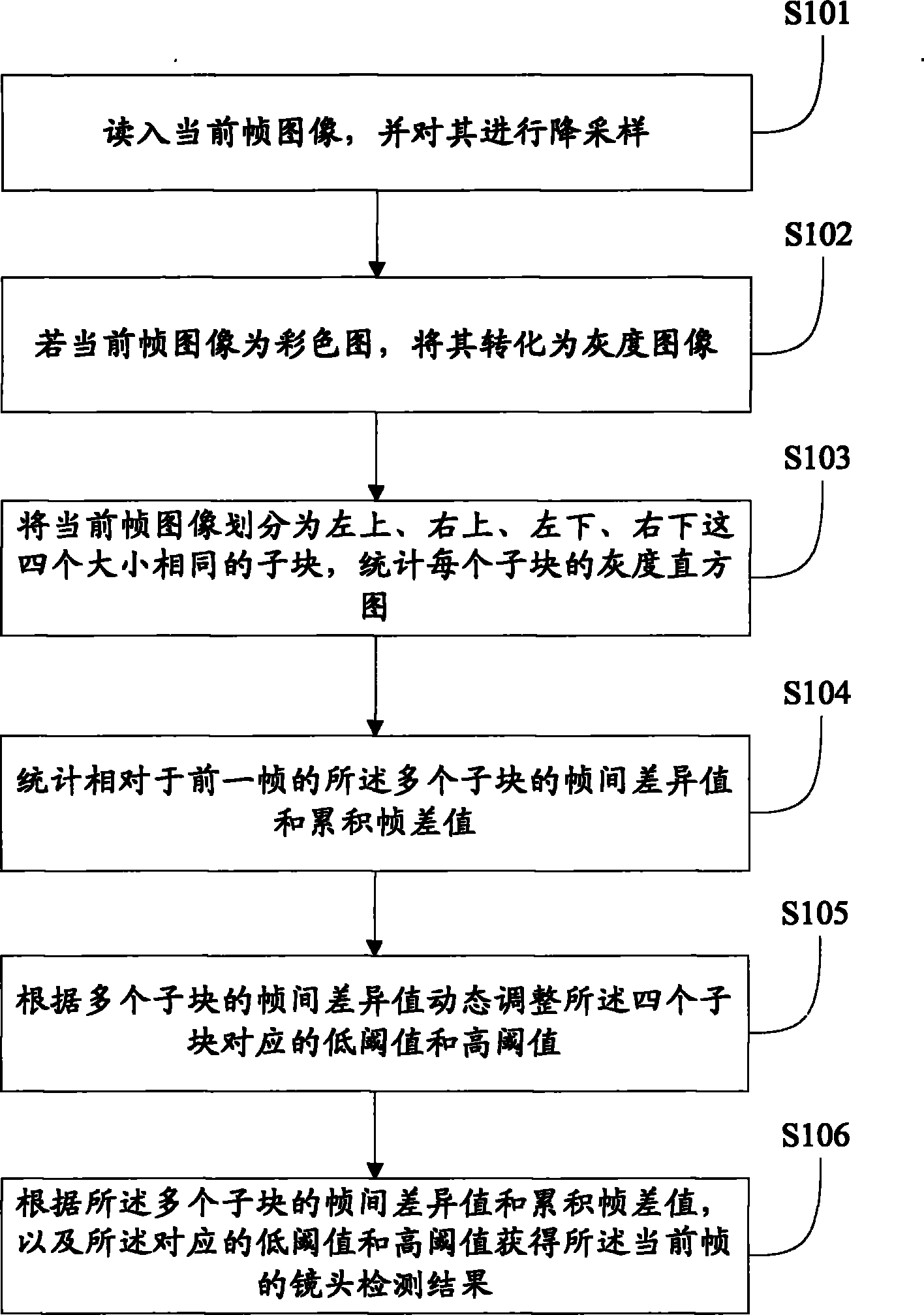
  • Method and device for detecting lens in real time in fully automatic two-dimensional (2D) to three-dimensional (3D) technology
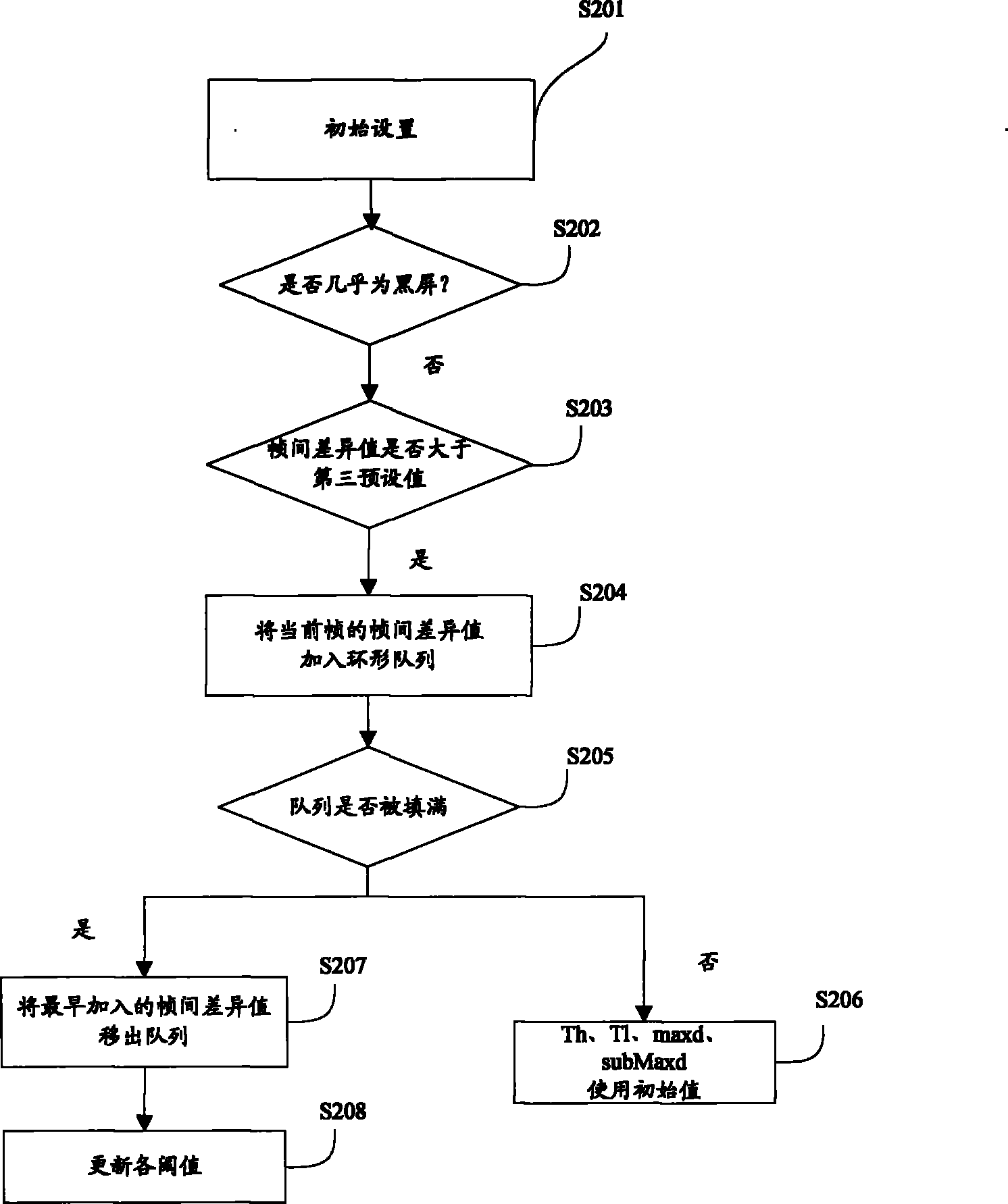
  • Method and device for detecting lens in real time in fully automatic two-dimensional (2D) to three-dimensional (3D) technology
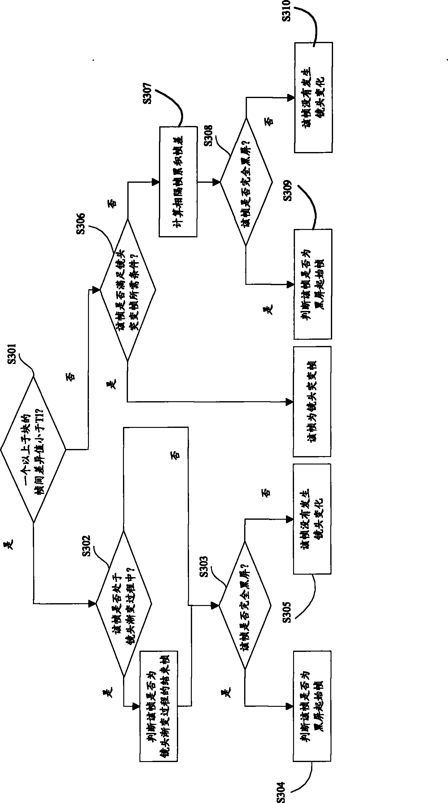
  • Method and device for detecting lens in real time in fully automatic two-dimensional (2D) to three-dimensional (3D) technology

Examples


Embodiment Construction

[0018] Embodiments of the present invention are described in detail below, examples of which are shown in the drawings, wherein the same or similar reference numerals designate the same or similar elements or elements having the same or similar functions throughout. The embodiments described below by referring to the figures are exemplary only for explaining the present invention and should not be construed as limiting the present invention.

[0019] The invention is based on a double-threshold algorithm and improves the double-threshold algorithm. In order to have a clear recognition and understanding of the present invention, the dual-threshold algorithm is briefly introduced below. The double-threshold method sets two thresholds T b and T s , where T b >T s , the frame difference between the current frame and the next frame is greater than T b When there is a sudden change in the lens, and the frame difference between the previous frame and the next frame is less than ...


PUM


Abstract

The invention discloses a method for detecting a lens in real time in fully automatic two-dimensional (2D) to three-dimensional (3D) technology. The method comprises the following steps of: reading a current frame; partitioning the current frame into a plurality of sub-blocks; counting inter-frame difference values and accumulated frame difference values of the plurality of sub-blocks relative to a previous frame; dynamically adjusting corresponding low threshold values and high threshold values of the plurality of sub-blocks according to the inter-frame difference values of the plurality of sub-blocks; and obtaining a lens detection result of the current frame according to the inter-frame difference values and the accumulated frame difference values of the plurality of sub-blocks and the corresponding low threshold values and high threshold values. The method has the advantages of giving the lens detection result of the current frame on line in real time, achieving a high recall ratio on the basis of ensuring a precision ratio and basically meeting the requirement of subsequent processing.

Description

technical field [0001] The invention relates to the field of computer multimedia technology, in particular to a real-time lens detection method and device in fully automatic 2D to 3D technology. Background technique [0002] A shot in a video refers to a sequence of frames that are continuously shot by the same camera and represent a continuous action in time and space. From the perspective of context semantic content, shot is the basic unit of video sequence content. For a real-time fully automatic 2D to 3D system, a common process is to divide it into three steps: lens detection, depth calculation and DIBR rendering. Among them, shot detection requires the ability to simultaneously detect the boundaries of shot changes and shot gradients in the video; depth calculation is based on shot detection, and for adjacent image frames in the same shot, it is processed by block matching algorithm and bilateral filtering. , to obtain an approximate depth map; while DIBR rendering r...

Claims


Application Information

Patent Timeline
IPC IPC(8): H04N17/00H04N13/00
Inventor 戴琼海晏希
Owner TSINGHUA UNIV
Why Eureka
Eureka Blog
Learn More