
Constant current source, power circuit and illuminating system

A technology of power supply circuit and constant current source, applied in the field of power supply, can solve the problems of large volume, poor stability and low lifespan, and achieve the effect of reducing the volume, improving the lifespan and working stability.

Inactive Publication Date: 2010-12-15
SHENZHEN SED IND +1
View PDF4 Cites 0 Cited by
  • Summary
  • Abstract
  • Description
  • Claims
  • Application Information

AI Technical Summary

Problems solved by technology

[0003] The purpose of the embodiments of the present invention is to provide a constant current source, aiming to solve the problems of large volume, low life and poor stability in the existing constant current source technology

Method used


Image

  • Constant current source, power circuit and illuminating system
  • Constant current source, power circuit and illuminating system
  • Constant current source, power circuit and illuminating system

Examples


Embodiment 1

[0026] figure 1 A structural principle diagram of a constant current source provided by an embodiment of the present invention is shown, and only parts related to the embodiment of the present invention are shown for convenience of description.

[0027] Non-polar capacitor C IN , its first end is connected to the positive pole VBUS+ of the DC power supply, and its second end is connected to the negative pole VBUS- of the DC power supply for filtering the input voltage;

[0028] Constant current drive circuit 11, its input terminal is connected with the non-polar capacitor C IN The first terminal and the second terminal are respectively connected to convert the input voltage into a constant current;

[0029] Inductor LOUT, the first end of which is connected to the output end of the constant current drive circuit 11 for filtering the output current;

[0030] Non-polar capacitor C OUT , its first terminal is connected to the output terminal of the constant current drive circ...

Embodiment 2

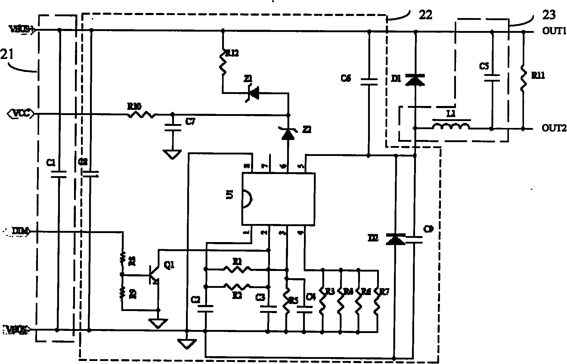
[0035] figure 2 A circuit diagram of a constant current source provided by an embodiment of the present invention is shown, and only parts related to the embodiment of the present invention are shown for convenience of description.

[0036] Input unit 21:

[0037] It includes a non-polar capacitor C1, whose first end is connected to the positive pole VBUS+ of the DC power supply, and whose second end is connected to the negative pole VBUS- of the DC power supply for filtering the input voltage.

[0038] The DC-DC constant current drive circuit 22 is connected to the input terminal 21 and is used to convert the input voltage into a constant current.

[0039] Output unit 23:

[0040] Including an inductor L1 connected to the DC-DC constant current drive circuit 22 for filtering the output current;

[0041] The non-polar capacitor C5, its first end is respectively connected to the DC-DC constant current drive circuit 22 and the first output end OUT1 of the constant current so...


PUM


Abstract

The invention is suitable for the field of power supplies, in particular relates to a constant current source and provides the constant current source. The constant current source comprises a nonpolar capacitor CIN, a constant current driving circuit, an inductor LOUT and a nonpolar capacitor COUT, wherein the nonpolar capacitor CIN is used for filtering an input voltage; the constant current driving circuit is used for converting the input voltage into a constant current; the inductor LOUT is used for filtering an output current; and the nonpolar capacitor COUT is used for filtering the output current. The constant current source solves the problems of large volume, short service life, unstable operation and the like in the conventional constant current source technology by substituting the nonpolar capacitor for an electrolytic capacitor in the conventional constant current source, so that the constant current source has reduced size, prolonged service life, and improved operation stability.

Description

technical field [0001] The invention belongs to the field of power supply, and in particular relates to a constant current source, a power supply circuit and a lighting system. Background technique [0002] There are two types of existing constant current sources: linear power supply improved constant current source and switching power supply constant current source with electrolytic capacitors. A common component of these power supplies is electrolytic capacitors. This type of capacitor has the disadvantages of large size, low life, and poor stability. Contents of the invention [0003] The purpose of the embodiments of the present invention is to provide a constant current source, aiming at solving the problems of large volume, low lifespan and poor stability existing in the existing constant current source technology. [0004] The embodiment of the present invention is achieved in this way, a constant current source, the constant current source includes: [0005] Non-...

Claims


Application Information

Patent Timeline
IPC IPC(8): H05B37/00H02M1/14
Inventor 范传玺
Owner SHENZHEN SED IND
Learn More