
Vehicle-mounted explosion-proof hydraulic winch
A hydraulic winch and vehicle-mounted technology, which is applied in hoisting devices, clockwork mechanisms, etc., can solve problems such as loose structures, many floor undulations, and large up and down slopes
- Summary
- Abstract
- Description
- Claims
- Application Information
AI Technical Summary
Problems solved by technology
Method used
Image

Examples
Embodiment Construction
[0016] The present invention will be further described below in conjunction with accompanying drawing:
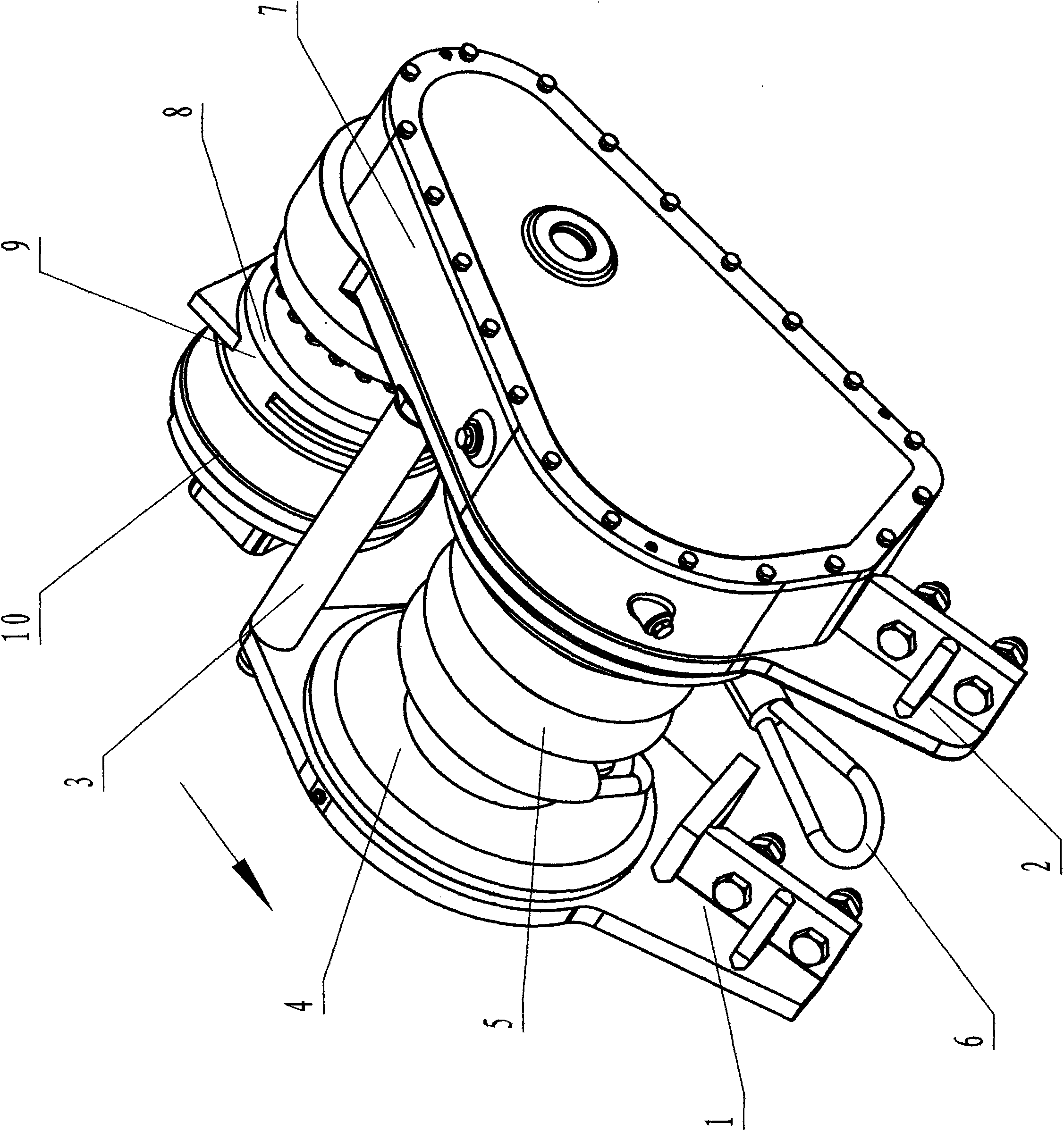
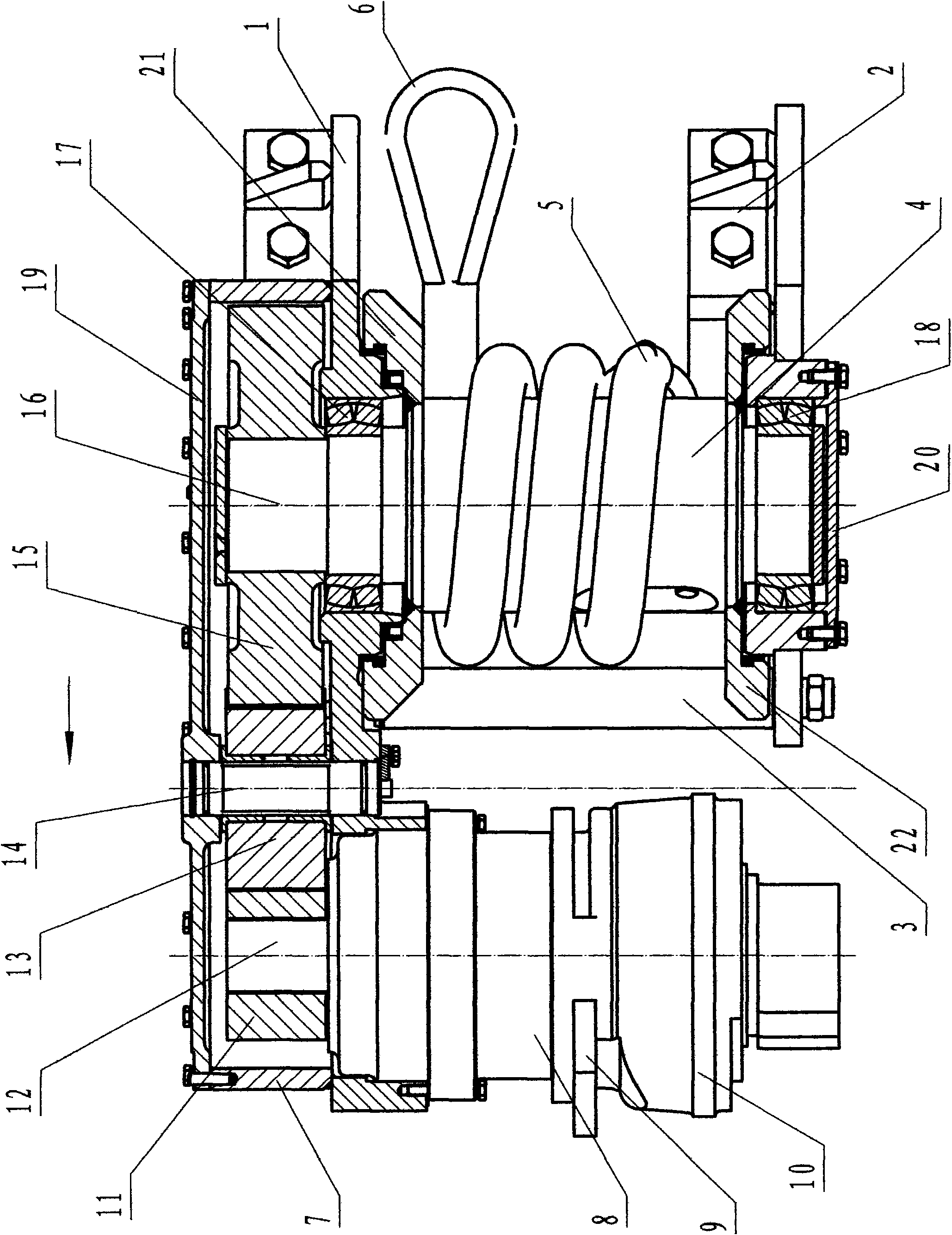
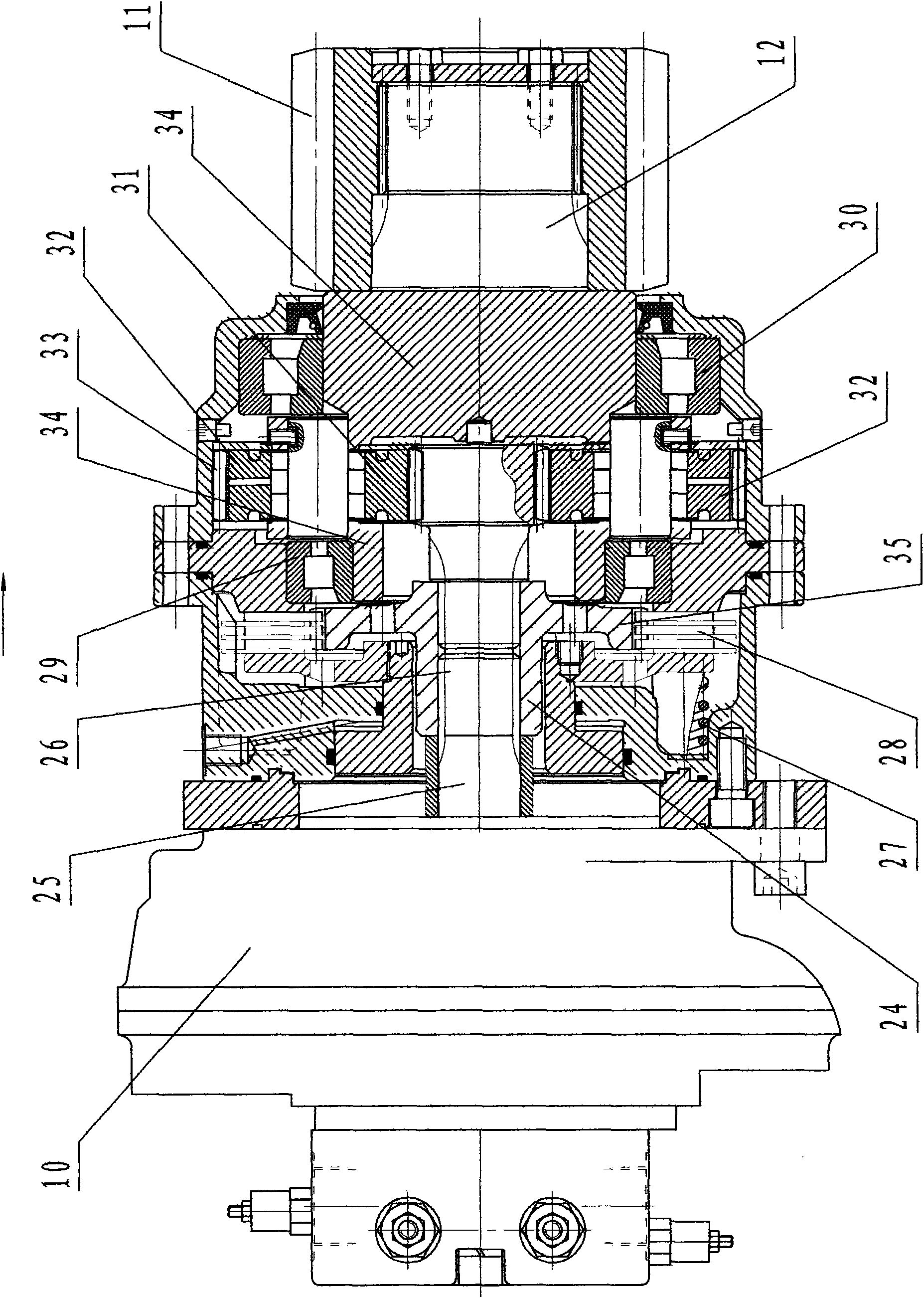
[0017] figure 1 , 2 . As shown in 3, it is the overall structure diagram. The position and relationship of each part must be correct and the installation should be firm.
[0018] The first support 1, the second support 2, and the support rod 3 form an integral frame. Between the first support 1 and the second support 2 are the support rod 3 and the roller 4, and the first and second The baffles 21 and 22 are positioned, the cable 5 is wound on the drum 4, and the front end of the cable 5 is a pulling ring 6; the main reducer 7 is installed on the first support 1 on the left part of the drum 5, and the other end of the main reducer 7 is connected to the planetary reducer 8. The planetary reducer 8 is connected to the brake 9, and the brake 9 is connected to the hydraulic motor 10;
[0019] The main reducer 7 is equipped with a driving gear 11 on the driving wheel shaft 12...
PUM
 Abstract
Description
Claims
Application Information