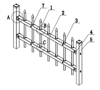
Assembled triangle pipe fence
A triangular tube, assembled technology, applied to the fence. It can solve the problems of weak resistance to lateral force, easy to break through, complex assembly, etc., to achieve the effect of reducing weight, broadening the scope of use and market, and improving the performance of lateral force resistance.
- Summary
- Abstract
- Description
- Claims
- Application Information
AI Technical Summary
Problems solved by technology
Method used
Image

Examples
Embodiment 1
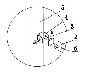
[0035] Embodiment 1: The clamping device adopts an insert structure.
[0036] Such as Figure 4 to Figure 7 As shown, a through "T"-shaped hole 103 is opened on the triangular bottom wall of the vertical column 101 and the corner wall corresponding to the bottom edge. On the upper wall of the assembly position of column 2, the horizontal hole part of the inverted "T" shaped hole 103 in the lower part of the vertical column 101 is located under the lower wall of the assembly position of the lower horizontal column 2. When assembling, first place the horizontal column 2 in a suitable position , then will be as Figure 5 , Figure 6 The insert 102 shown is inserted vertically through the vertical hole portion of the “T”-shaped hole 103, and then rotated 90 degrees so that it falls into the horizontal hole portion of the “T”-shaped hole 103 and is firmly supported. Such as Figure 5 to Figure 7 As shown, the supporting part 104 and the supporting part 106 at both ends of the i...
Embodiment 2
[0037] Embodiment 2: The clamping device adopts a shrapnel structure.
[0038] Such as Figure 8 to Figure 10 As shown, a rectangular hole 202 is provided on the triangular bottom side wall of the vertical bar 201, and the vertical bar 201 is inserted into a Figure 9 The shown shrapnel 203, the shrapnel 203 is bent by a spring steel sheet into the shape of the rear V-shaped part 204 and the front protruding support part 205. After assembly, it is shown as Figure 10 As shown, the front protruding support part 205 pops out from the rectangular hole 202 to form a support for the horizontal bar, and the rear V-shaped part 204 fits with the inner walls of the triangular sides of the vertical bar 201, so that the elastic piece 203 can effectively support inside the triangular tube. Insert the upper and lower parts of each vertical bar 201 into the two elastic pieces 203 to the pop-up position. During the overall assembly, you only need to press down the protruding support part 2...
Embodiment 3
[0039] Embodiment 3: The clamping device adopts a spring column structure.
[0040] Such as Figure 11 to Figure 14As shown, the spring post structure includes an assembled pop-up spring post 302, a spring 303, and a rear cap 304. The pop-up spring post 302 is a column with steps, and a counterbore is provided at the center of its bottom surface, and its aperture is slightly larger than that of the spring 303. diameter; the center of the bottom surface of the back cap 304 is also provided with a counterbore, and its aperture is slightly larger than the diameter of the pop-up spring post 302, and the top surface of the back cap 304 has two symmetrical slopes, and the angle between the slopes is formed by the triangle two waists of the vertical bar 301 Same top angle. Such as Figure 12 As shown, a round hole is opened on the bottom side wall of the vertical bar 301, and the front column of the pop-up spring post 302 pops out from the round hole, and its step blocks the inner ...
PUM
 Abstract
Description
Claims
Application Information
 - R&D Engineer
- R&D Manager
- IP Professional
- Industry Leading Data Capabilities
- Powerful AI technology
- Patent DNA Extraction
Browse by: Latest US Patents, China's latest patents, Technical Efficacy Thesaurus, Application Domain, Technology Topic.
© 2024 PatSnap. All rights reserved.Legal|Privacy policy|Modern Slavery Act Transparency Statement|Sitemap