Shifting fork shaft and manufacturing method thereof

A manufacturing method and a technology of shift fork shafts, which are applied in the direction of manufacturing tools, transmission control, grinding machines, etc., can solve problems such as hindering normal use, blackening of the surface of the shifting chute, and stuck shifting steel balls or shafts, etc. Achieve excellent high reliability and stability, excellent surface processing accuracy, and avoid the effect of shifting failure accidents

Inactive Publication Date: 2010-12-22
林加伟
View PDF8 Cites 6 Cited by
  • Summary
  • Abstract
  • Description
  • Claims
  • Application Information

AI Technical Summary

Problems solved by technology

[0002] The surface of the shift chute on the traditional shift fork shaft is first formed by milling and then quenched. The quenching treatment will make the surface of the shift chute black and rough. This traditional shift fork shaft It is widely used in practice, but it is easy to get stuck with the gear shift steel ball or shaft that matches it, resulting in gear shift failure and hindering its normal use.

Method used


Image

  • Shifting fork shaft and manufacturing method thereof
  • Shifting fork shaft and manufacturing method thereof
  • Shifting fork shaft and manufacturing method thereof

Examples


Embodiment 1

[0021] (Embodiment 1, shift fork shaft)

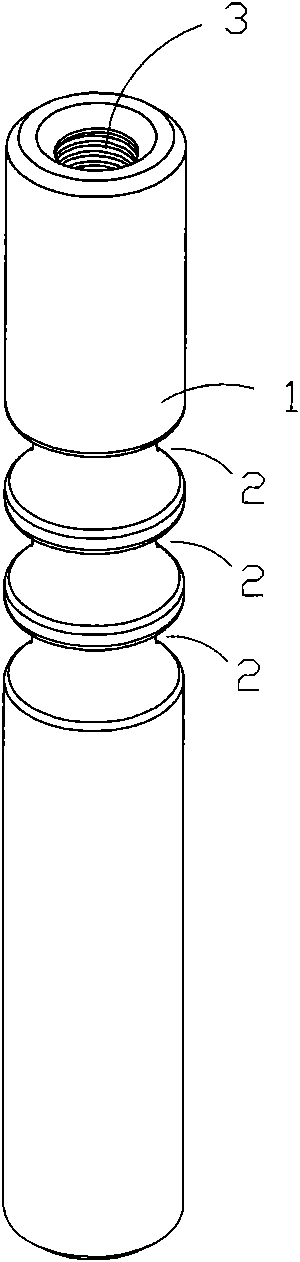
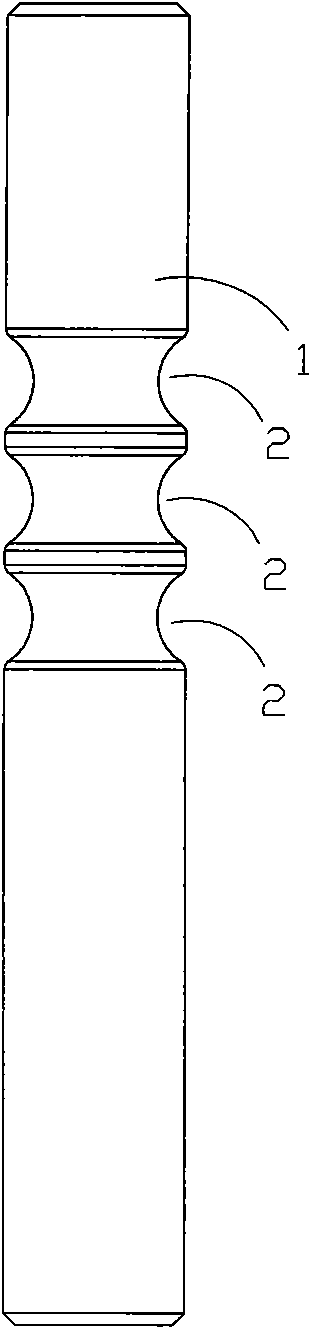
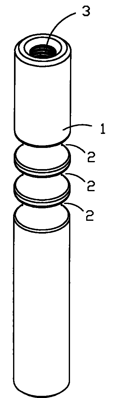
[0022] figure 1 and figure 2 A specific embodiment of the invention is shown in which, figure 1 It is a schematic diagram of a three-dimensional structure of the product of the present invention; figure 2 for figure 1 A front view of the fork shaft shown.

[0023] This embodiment is a shift fork shaft used on agricultural machinery, which is provided with a cylindrical work area 1, and three shift chute 2 are arranged on the work area 1; two axial directions of the shift fork shaft The side end is provided with mounting screw holes 3, and the basic shape of the axial section of each shift chute 2 is arc-shaped, which is semicircular in this embodiment, and the surface of each shift chute 2 is made of nylon. Smooth surface made by grinding with elastic grinding wheel.

[0024] Specifically, the smooth surface of each shift chute 2 is first formed by milling, then quenched, and finally polished with an elastic grinding wheel, so ...

Embodiment 2

[0025] (Example 2, manufacturing method of shift fork shaft)

[0026] This embodiment is a manufacturing method of the shift fork shaft described in Embodiment 1, comprising the following steps:

[0027] ① Select the steel column blank, process the mounting screw holes 3 on both sides of the blank in the axial direction, and mill out a predetermined number of shift chute 2 at its predetermined position;

[0028] ② Perform power frequency quenching treatment on the blank of the milled shift chute 2 to increase the hardness of the shift chute 2;

[0029] ③ Grinding the quenched blank, specifically, using an elastic grinding wheel to grind the shift chute 2, after the surface of the shift chute 2 changes from rough and black to smooth and reflective, it can be used as a finished shift fork shaft; The elastic grinding wheel can be selected from fiber grinding wheel, cloth wheel, or wool wheel, and is further preferably a nylon fiber grinding wheel; in this step, stop grinding whe...


PUM

PropertyMeasurementUnit
surface roughnessaaaaaaaaaa

Abstract

The invention discloses a shifting fork shaft and a manufacturing method thereof. The shifting fork shaft is provided with a cylindrical working area, a plurality of shifting chutes are arranged on the working area, the axial cross section of each shifting chute is in the basic shape of a circular arc, and the surface of each shifting chute is a smooth surface ground by an elastic grinding wheel. The manufacturing method comprises the following steps: (1) selecting a steel column billet, and milling a preset amount of shifting chutes on the steel column billet; (2) quenching the billet on which the shifting chutes are milled to improve the hardness of the shifting chutes; and (3) grinding the quenched billet: concretely, grinding the shifting chutes by adopting the elastic grinding wheel, and taking the shifting chutes as the finished products of shifting fork shafts after the surfaces of the shifting chutes are changed from a rough and black state into a smooth and light-reflecting state. The product of the invention has high reliability and stability, and the process of the invention has better simplicity and convenience.

Description

technical field [0001] The invention belongs to the technical field of shift fork shaft processing and manufacturing, and in particular relates to a shift fork shaft for gear shifting and a manufacturing method thereof. Background technique [0002] The surface of the shift chute on the traditional shift fork shaft is first formed by milling and then quenched. The quenching treatment will make the surface of the shift chute black and rough. This traditional shift fork shaft It is used in a large number in practice, but it is easy to get stuck on the shift steel ball or shaft rod matched with it, resulting in gear shift failure and hindering its normal use. Contents of the invention [0003] The object of the present invention is to provide a shift fork shaft with high reliability and stability and its manufacturing method. [0004] The technical solution to achieve the first purpose of the present invention is: a shift fork shaft with a cylindrical working area, and a plu...

Claims


Application Information

Patent Timeline
Patent Type & Authority Applications(China)
IPC IPC(8): F16H59/02F16H63/30B23P15/00B24B19/00B24D13/00
Inventor 林加伟
Owner 林加伟
Why Eureka
Try Eureka