Wear-resisting ceramic pneumatic side sliding valve

A technology of wear-resistant ceramics and slide valves, which is applied to slide valves, valve devices, engine components, etc., and can solve problems such as external leakage, easy jamming, and environmental pollution

Inactive Publication Date: 2010-12-22
周根章
View PDF0 Cites 1 Cited by
  • Summary
  • Abstract
  • Description
  • Claims
  • Application Information

AI Technical Summary

Problems solved by technology

Its anti-wear and corrosion resistance is poor, it is easy to get stuck, and it is very easy to damage. Usually, the valve will be blown out within a few hours...

Method used


Image

  • Wear-resisting ceramic pneumatic side sliding valve
  • Wear-resisting ceramic pneumatic side sliding valve

Examples


specific Embodiment approach

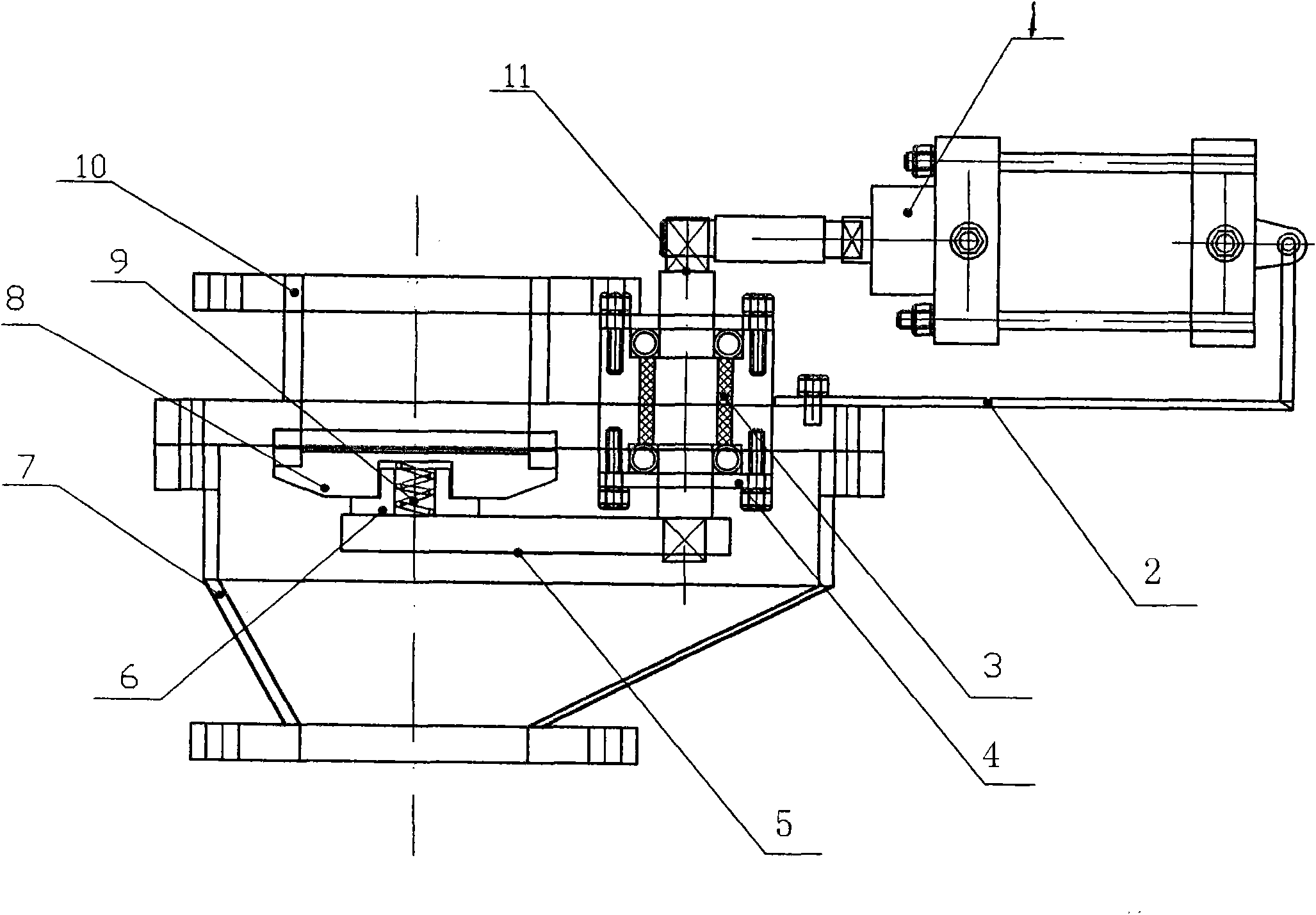
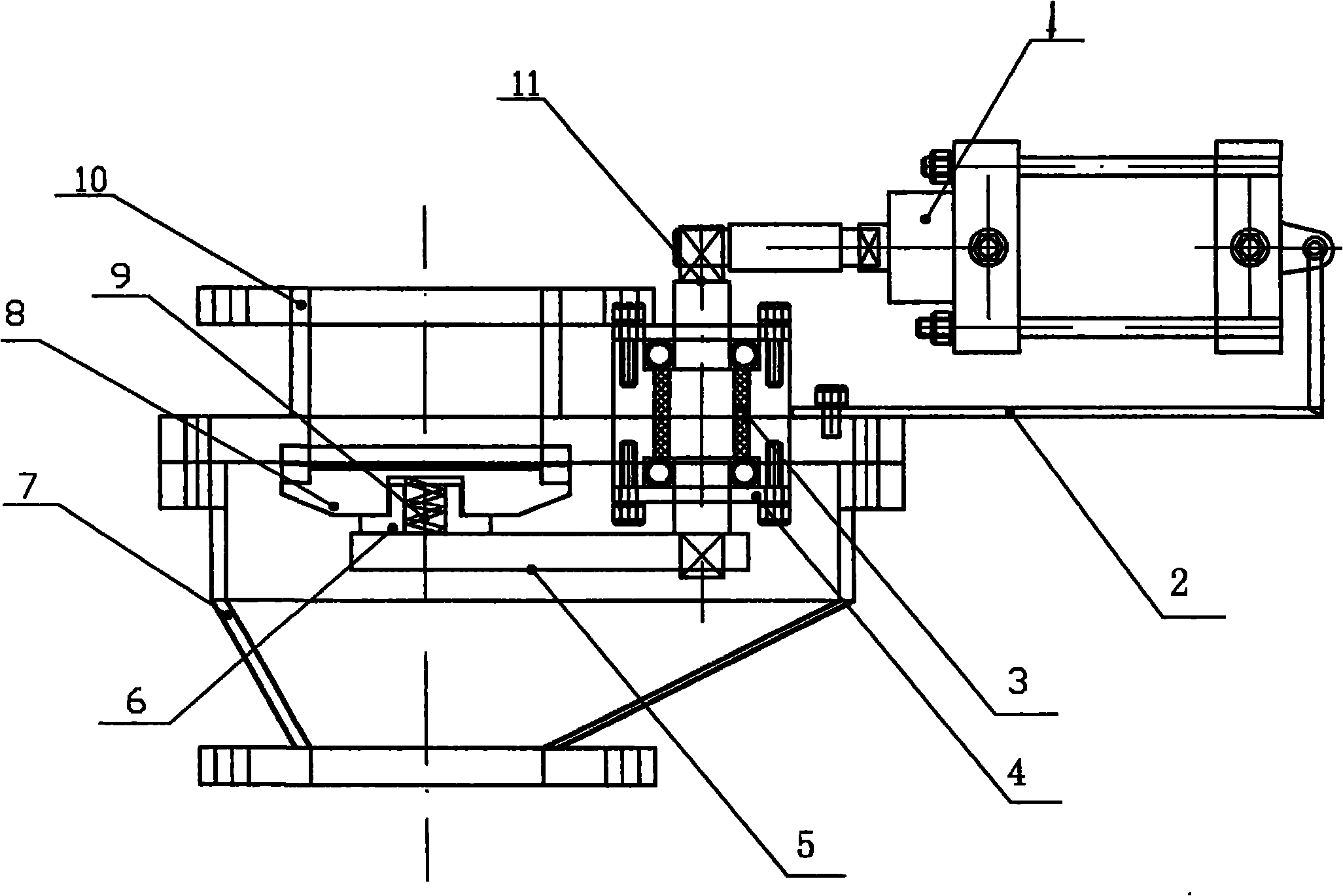
[0006] Specific embodiments: the present invention will be further described below in conjunction with accompanying drawing

[0007] In the figure, a wear-resistant ceramic pneumatic side slide valve of the present invention uses the rotating shaft as the fulcrum, and the horizontal force arm lever moves under the rotation of the rotating shaft so that the ceramic pendulum side slide plate is closely attached to the upper and lower valve bodies. This design can effectively scrape off the sundries on the surface of the ceramic pendulum side slide; in addition, this device adopts the buoyancy technology that assists the compensation spring to cooperate with the ceramic pendulum side slide, which can ensure that the ceramic pendulum side slide is tightly connected to the upper valve body. Contact without any gaps, and there will be no air leakage. During specific implementation, the action execution cylinder is fastened on the cylinder bracket to drive the rotating shaft to rotat...


PUM


Abstract

The invention relates to a wear-resisting ceramic pneumatic side sliding valve, which comprises an upper valve body, a lower valve body, an air cylinder, an air cylinder support, a sealing member, a rotating shaft and a lever, wherein through arranging a ceramic balancing point side sliding plate between the upper valve body and the lower valve body, the rotation of an air cylinder shaft drives the rotating shaft to rotate to ensure that the lever connected with the rotating shaft and the ceramic balancing point side sliding plate rotate together with the rotating shaft, the horizontal action force generated by the sliding of a ceramic balancing point side can effectively push and crape residues; meanwhile, an assisting compensating spring is adopted to ensure that the ceramic balancing point plate flexibly rotates under the action of floating force, which effectively prevents from phenomena of stoppage, biting and blockage caused by sediment scaling so as to thoroughly solve the problem that the ceramic balancing point plate can not normally act.

Description

Technical field: [0001] The invention relates to a wear-resistant ceramic pneumatic side slide valve. The valve relates to the technical field of feeding and discharging opening and closing and automatic control devices used in a pneumatic conveying system. Background technique: [0002] In the field of industrial production, the opening and closing valves of the feeding and discharging materials in the pneumatic conveying system equipment are all key components, because the working principle of pneumatic conveying is a system composed of warehouse pumps, valves, pipes and control electrical appliances. Send powder or granular materials to their destinations. Because pneumatic conveying is a kind of conveying principle of air pressure blowing materials, the erosion and wear of the opening and closing control valves of feeding and discharging materials are very large; at the same time, because the relative humidity in the compressed air changes greatly, the ash powder being ...

Claims


Application Information

Patent Timeline
IPC IPC(8): F16K3/02B65G53/46
Inventor 周根章
Owner 周根章
Why Eureka
Try Eureka