Cement mortar stirring device

A mixing device and cement mortar technology, applied in the field of cement mixing, can solve the problems of inconvenient disassembly, difficult cleaning, easy solidification, etc., and achieve the effect of convenient and convenient replacement

Inactive Publication Date: 2019-01-11
广德县坚固水泥制品有限公司
View PDF5 Cites 0 Cited by
  • Summary
  • Abstract
  • Description
  • Claims
  • Application Information

AI Technical Summary

Problems solved by technology

Both types of mixers are used for many purposes other than concrete and mortar, such as kneading fertilizer, nursery soil, etc. Therefore, when kneading cement, sand, water, gravel, etc. with these mixers, there is a disadvantage that the kneading time is relatively long, Moreover, the traditional mixing blade structure is easy to be stained with sand and gravel during the mixing process, which is easy to solidify and difficult to clean. At the same time, it is inconvenient to disassemble during maintenance and overhaul, which affects work efficiency.

Method used


Image

  • Cement mortar stirring device
  • Cement mortar stirring device
  • Cement mortar stirring device

Examples


Embodiment 1

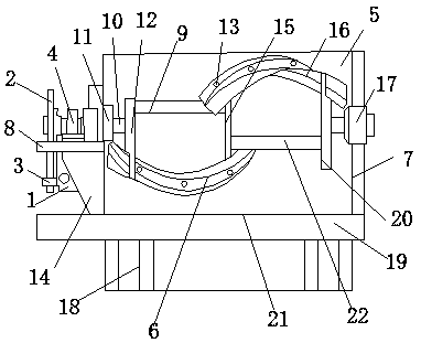
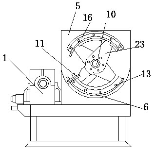
[0024] Example 1: Reference Figure 1-2 , a cement mortar mixing device, including a tank body 21, a prime mover 1, a blade body A6 and a blade body B16, and a side wall sliding contact body 11; the lower surface of the tank body 21 is fixedly connected to the upper surface of the fixed shaft 19, fixed The lower surface of the shaft 19 is fixedly connected with the upper end of the support column 18, the left outer surface of the tank body 21 is fixedly connected with the baffle 8, the left end of the baffle 8 is fixedly connected with the sprocket 2, and the lower surface of the baffle 8 is connected with the upper end of the prime mover baffle 14. Fixed connection, the right side of the prime mover baffle 14 is fixedly connected to the left side of the tank body 21, the prime mover 1 is fixedly installed on the lower surface of the baffle 8, the chain 3 is fixedly installed at the lower end of the sprocket 2, and the upper surface of the baffle 8 is fixedly installed. Rotati...

Embodiment 2

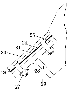
[0027] Embodiment 2: refer to Figure 3-4 , combined with the basis of Embodiment 1, the side wall sliding contact body 11 includes a support arm 29 and a screw rod 28, the upper end of the support arm 29 is fixedly connected to the inner wall of the left side of the tank body 21, the lower end of the support arm 29 is fixedly connected to the upper end of the fixed plate 25, and fixed The lower surface of the plate 25 is fixedly connected with the slidable rubber plate 24, the lower surface of the slidable rubber plate 24 is provided with a synthetic resin cloth 26, the lower surface of the synthetic resin cloth 26 is fixedly connected with a plastic rubber plate 31, and the lower surface of the plastic rubber plate 31 is fixedly connected with a The polymer plate 30, the bottom end of the screw rod 28 runs through the fixed block 25, the slidable rubber plate 24, the synthetic resin cloth 26 and the plastic rubber plate 31 are fixedly connected with the inner bottom surface o...


PUM


Abstract

The invention discloses a cement mortar stirring device, and belongs to the technical field of cement stirring. According to the cement mortar stirring device, a connecting rod A and a connecting rodB are respectively fixed at one ends of a vane body A and a vane body B; at the other ends, the vane body A and the vane body B are fixedly connected with the upper end and the lower end of a fixed connecting rod respectively, and rotation of a rotating shaft is driven by the power of a prime motor, so as to drive the rotation of the vane body A and the vane body B, and effectively scrape matterson the inner wall of the tank, and therefore, kneading material attached to the surface of the tank is tripped all the time; compared with the prior art, accumulated precipitate is used a resistance element for hindering rotation, and inconvenience of reduction of stirring performance is solved. In addition, because cement and the like can be prevented from attaching to the inner side of the tank,the used stirring device is easy to clean and can be simplified for maintenance.

Description

technical field [0001] The invention relates to the technical field of cement mixing, in particular to a cement mortar mixing device. Background technique [0002] Usually, when kneading mortar cement or the like, a Tarai type mortar mixer, tank concrete mixer or the like is used. In addition to concrete and mortar, both mixers are used for many purposes, such as kneading fertilizers, nursery soil, etc., therefore, when these mixers are used to knead cement, sand, water, gravel, etc., there is a disadvantage that the kneading time is relatively long, In addition, the traditional stirring blade structure is easy to stain with sand and gravel during the stirring process, which is easy to solidify and difficult to clean. SUMMARY OF THE INVENTION [0003] The invention proposes a mixing device in a concrete mortar mixer, which can reasonably knead the cement, sand, water, gravel and other substances in a short time, and is easy to disassemble and assemble for cleaning. [00...

Claims


Application Information

Patent Timeline
Patent Type & Authority Applications(China)
IPC IPC(8): B28C5/08B28C5/14B01F15/00
CPCB28C5/0806B28C5/14B01F35/123
Inventor 吴敏丁文强徐明杰
Owner 广德县坚固水泥制品有限公司
Why Eureka
Try Eureka