Solar water heater overfilling-prevention and emptying device
A technology of solar water heater and emptying device, which is applied in the fields of anti-overflow and emptying of ordinary water tanks, and anti-overflow of solar water heater water pipes. It can solve the problems of bursting of upper and lower water pipes, inconvenient installation, inconvenient maintenance, etc., and achieve the effect of strong antifreeze performance
- Summary
- Abstract
- Description
- Claims
- Application Information
AI Technical Summary
Problems solved by technology
Method used
Image
Examples
Embodiment 1
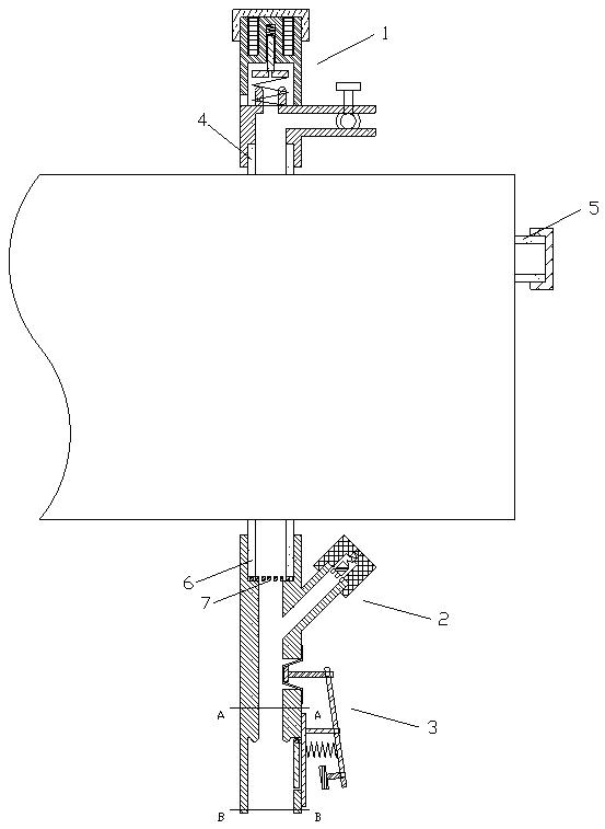
[0054] An anti-overflow and emptying device for a solar water heater is composed of a pressure control unit [1], an emptying check valve [2] and a pressure valve [3]. Assembly diagram as figure 1 shown.
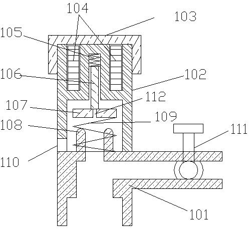
[0055] The pressure control unit [1] is installed on the exhaust port [4] or overflow port [5] of the solar water heater tank, and another opening is closed; when the pressure in the solar water heater tank exceeds the design pressure, the pressure control unit [1] The decompression mechanism of the pressure control unit [1] is opened, and air enters the solar water heater tank, and the water flows from the The upper and lower nozzles [6] flow out, and the air intake mechanism of the pressure control unit is closed, so the water cannot flow out under the action of atmospheric pressure; a filter screen [7] is installed at the upper and lower nozzles [6], on the one hand, it can prevent sundries from entering the water tank, On the other hand, the surface tension of water can...
Embodiment 2
[0070] This embodiment provides another implementation of the pressure valve [3], and other components and structures are the same as those in Embodiment 1.
[0071] Such as Figure 4 As shown, the pressure valve [3] can also be composed of a pressure valve housing [301], a rotating cover plate [305], a cover plate base [306], a diaphragm [308], a pressing plate [307], a transmission mechanism [309] and a pressure valve The protective cover constitutes.
[0072] The middle of the pressure valve housing [301] is empty, as a water flow channel; A-A and B-B sections are as Figure 5 As shown; the pressure valve housing [301] has a control port [302], a rotating cover installation port [303] and a pressure plate installation port [304], and the rotating cover installation port [303] is located at the control port [302] by the water source end side; the rotating shaft of the rotating cover [305] is installed on the cover base [306], and a return spring is installed on the rotatin...
Embodiment 3
[0077] This embodiment provides another implementation of the pressure valve [3], and other components and structures are the same as those in Embodiment 1.
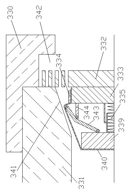
[0078] Such as Image 6 Shown, pressure valve [3] can be made of pressure valve housing [321][322], rotary cover plate [325], pressure piston mechanism and transmission mechanism [330].
[0079] The middle of the pressure valve housing [321] [322] is empty, as a water flow channel, the A-A section is as Image 6 As shown, the C-C section is as Figure 7 As shown, the D-D cross-section is a ring; the pressure valve housing [322] has a control port [323] and a pressure piston installation port [324]; the pressure valve housing [321] [322] is fixed together; the rotating cover [ The rotating shaft of 325] is installed on the pressure valve casing [322], and return spring is installed on the rotating shaft, provides the active force close to the inner wall of pressure valve casing [321] for rotating cover plate [325].
[...
PUM
 Abstract
Description
Claims
Application Information
 - R&D
- Intellectual Property
- Life Sciences
- Materials
- Tech Scout
- Unparalleled Data Quality
- Higher Quality Content
- 60% Fewer Hallucinations
Browse by: Latest US Patents, China's latest patents, Technical Efficacy Thesaurus, Application Domain, Technology Topic, Popular Technical Reports.
© 2025 PatSnap. All rights reserved.Legal|Privacy policy|Modern Slavery Act Transparency Statement|Sitemap|About US| Contact US: help@patsnap.com


