Rotary label and method for monitoring photolithographic quality using same

A marking and photolithography technology, which is applied in the direction of microlithography exposure equipment, optics, photoplate making process of pattern surface, etc., can solve problems such as difficult to distinguish

Active Publication Date: 2010-12-22
SHANGHAI HUAHONG GRACE SEMICON MFG CORP
View PDF0 Cites 8 Cited by
  • Summary
  • Abstract
  • Description
  • Claims
  • Application Information

AI Technical Summary

Problems solved by technology

This is because if the Figure 4 , Figure 5 As shown in the vernier caliper type rotating mark, after the projection mask with the rotating mark is exposed, when two adjacent exposure

Method used


Image

  • Rotary label and method for monitoring photolithographic quality using same
  • Rotary label and method for monitoring photolithographic quality using same
  • Rotary label and method for monitoring photolithographic quality using same

Examples


Embodiment Construction

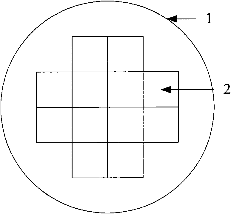
[0035] The rotation mark of the present invention is on the projection mask in the exposure step of the photolithography process, usually there is a rotation mark on the top, bottom, left and right of a projection mask.

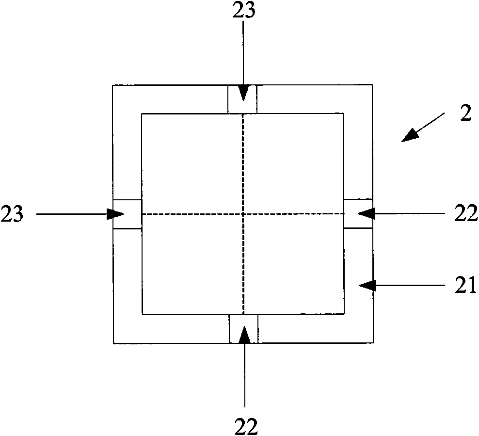
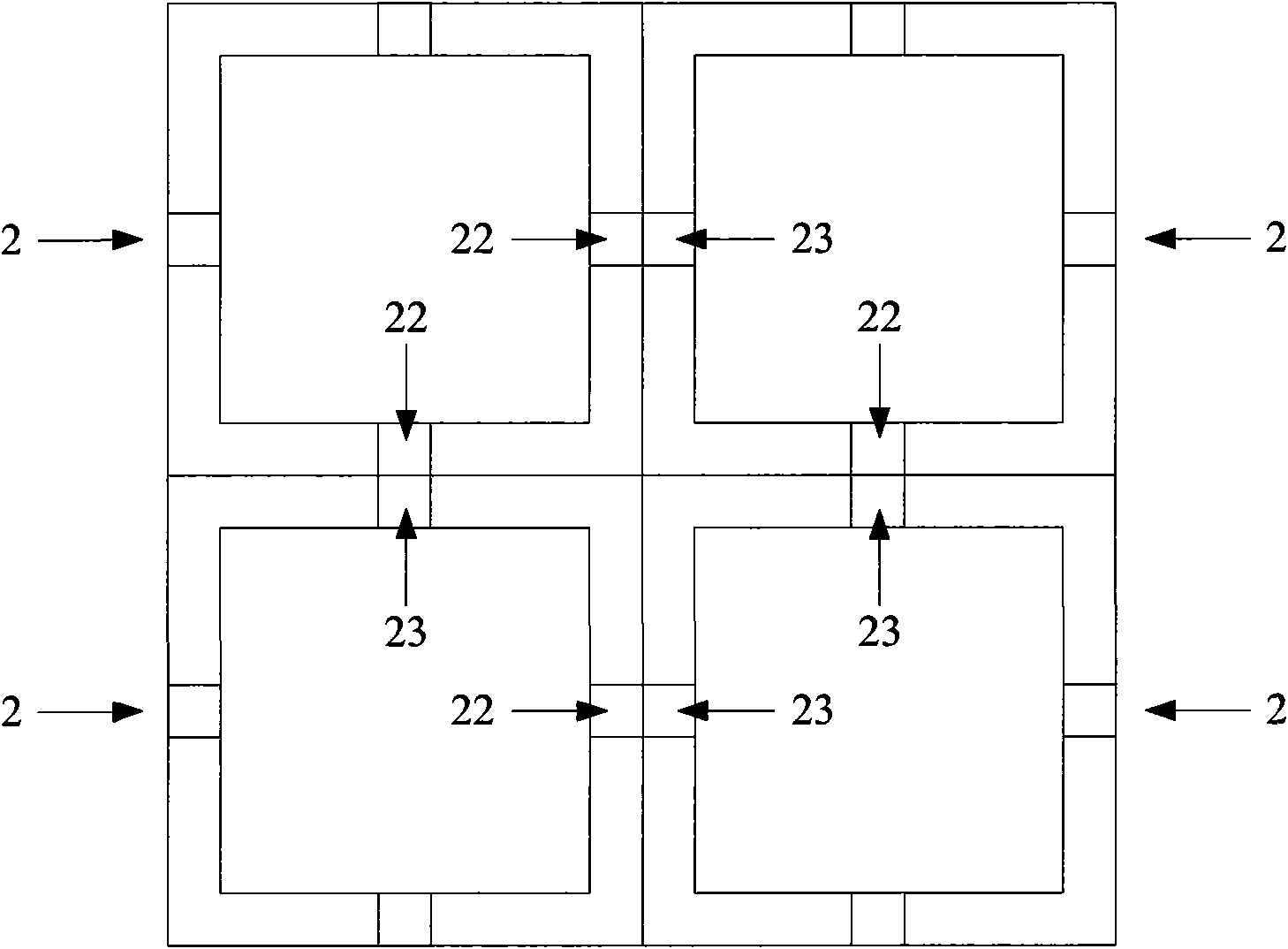
[0036] When there is a windmill-shaped cutting line on the projection mask, the windmill-shaped cutting line includes four pieces, and each cutting line has a rotation mark near the center line of the projection mask, such as Image 6 shown. After exposure, the two exposure units adjacent up and down have the graphics of two rotation marks adjacent to the left and right, and the two exposure units adjacent to the left and right have the graphics of two rotation marks adjacent up and down, such as Figure 7 shown.

[0037] see Figure 8 The rotary mark 5 of the present invention is a strip-shaped transparent zone 51 with equal width (set as a) on the opaque projection mask, and there is an equal width (set as b) between every two transparent zones 51. For t...


PUM

PropertyMeasurementUnit
Widthaaaaaaaaaa

Abstract

The invention discloses a rotary label, which refers to a plurality of strip-shaped transparent zones with an equal width on a non-transparent projection mask plate, wherein one non-transparent zone with an equal width is arranged between each two transparent zones; after the rotary label forms a pattern, the boundary which is a coincident part of the pattern of the rotary label and the pattern of an adjacent rotary label is called as a splicing boundary; in the rotary labels, the sum of the widths of the two transparent zones closest to the splicing boundary is equal to the width of the non-transparent zone between each two transparent zones; and each transparent zone has equal length or the length of the transparent zone closest to the splicing boundary is different from the lengths of other transparent zones. The invention also discloses a method for monitoring the photolithographic quality using the rotary label. The rotary label in the invention is suitable for a windmill-shaped cutting street, and the width of the windmill-shaped cutting street can be reduced to below 50mu m, thus being capable of reducing the ratio of the cutting street on a silicon wafer substantially.

Description

technical field [0001] The invention relates to a manufacturing process of a semiconductor integrated circuit, in particular to a rotary mark in the photolithography process and a method for detecting the quality of the photolithography using it. Background technique [0002] The photolithography process of semiconductor integrated circuits includes basic steps such as vapor phase base film formation, spin coating, soft baking, alignment and exposure, post-exposure baking, development, hard film baking, and development inspection. A projection reticle is required for the alignment and exposure steps. A projection mask is a transparent quartz slab with a pattern to be transferred to a photoresist layer on a silicon wafer. The projection mask only includes a part of the pattern on the silicon wafer, and this pattern must be repeated step by step to cover the entire silicon wafer. It is distinguished from a photomask or mask, which contains the entire array of chips on a sili...

Claims


Application Information

Patent Timeline
IPC IPC(8): G03F9/00G03F7/20
Inventor 阚欢
Owner SHANGHAI HUAHONG GRACE SEMICON MFG CORP
Why Eureka
Try Eureka