

Method and system for automatically generating anti-sabotage, anti-blocking, water irrigation, breathing, fire burning logic rules of substation
A generation system and substation technology, applied in the general control system, control/regulation system, information technology support system, etc., can solve the logic, hidden dangers, formation safety and other problems of missing switch status, so as to improve reliability and safety Effect
- Summary
- Abstract
- Description
- Claims
- Application Information
AI Technical Summary
Problems solved by technology
Method used
Image

Examples
Embodiment Construction
[0020] The specific embodiments of the self-generating method of the substation five defense logic rules and the self-generating system of the substation five defense logic rules of the present invention will be described in detail below.
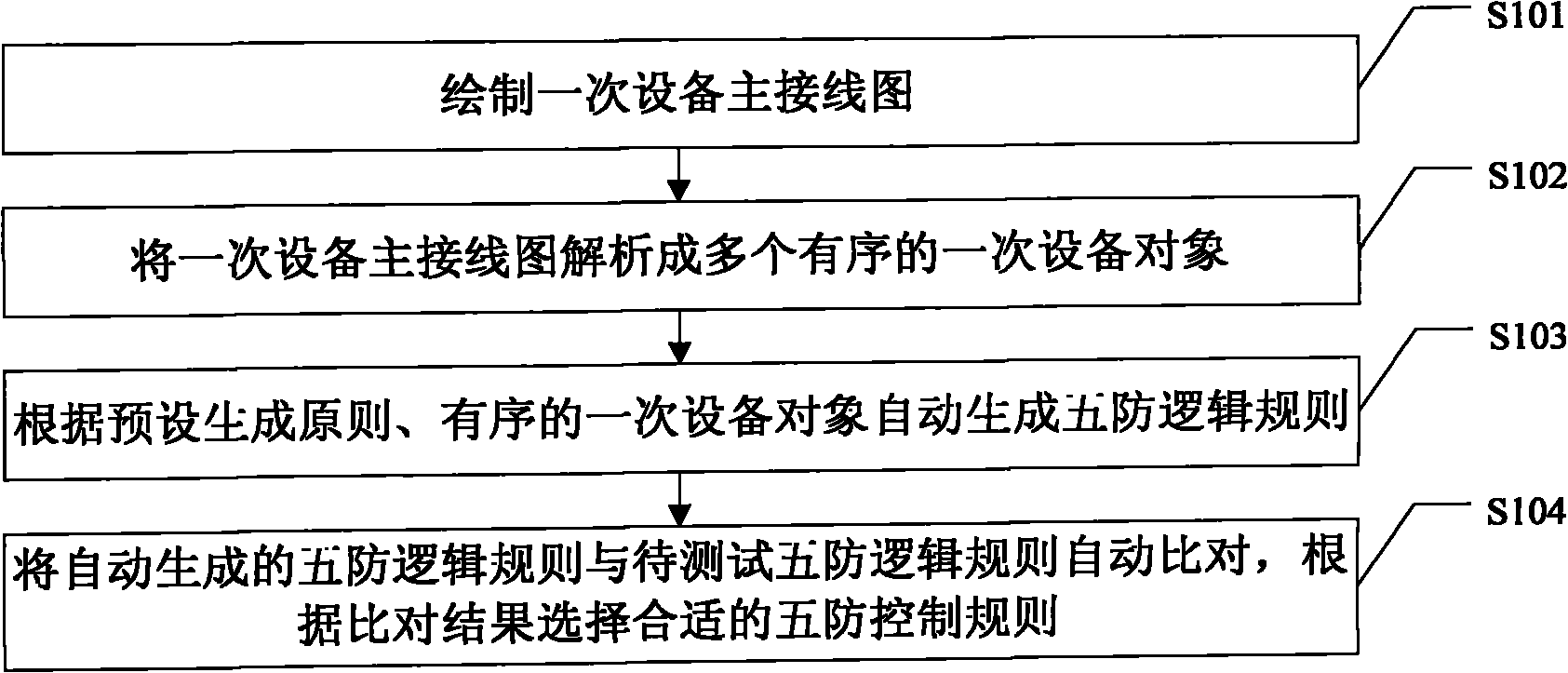
[0021] see figure 1 As shown, it is a schematic flow diagram of an embodiment of a method for self-generating substation five-defense logic rules of the present invention, which includes steps:
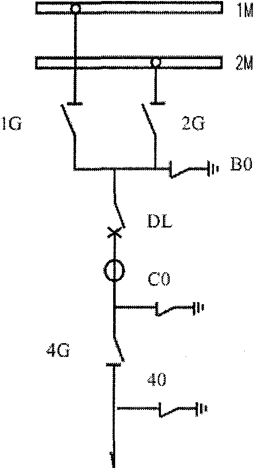
[0022] Step S101: draw the main wiring diagram of the equipment once, and enter step S102;
[0023] Step S102: Analyze the main wiring diagram of the primary equipment drawn above into multiple ordered primary equipment objects, and proceed to step S103;
[0024] Step S103: Automatically generate five defense logic rules according to the preset generation principle determined by the five defense principles and the logical relationship between the ordered primary equipment objects.
[0025] According to the self-generating method of substation fiv...
PUM
 Abstract
Description
Claims
Application Information