Permanent magnet and rolling-sliding bearing type motor rotor bearing and rotary machine with same

A motor rotor, rolling and sliding technology, applied in the direction of the casing/cover/support, electrical components, electromechanical devices, etc., can solve the problems of complex electronic control and manufacturing, low reliability, large friction loss of liquid sliding bearings, etc. The effect of reduced frictional power consumption and temperature rise, stable and reliable system operation, and improved service life

Inactive Publication Date: 2010-12-22
何君 +2
View PDF0 Cites 7 Cited by
  • Summary
  • Abstract
  • Description
  • Claims
  • Application Information

AI Technical Summary

Problems solved by technology

At present, for the bearing design of this kind of high-power, high-speed motor, it is generally considered to adopt the active magnetic bearing support method of the mixed support of electromagnetic bearing and rolling bearing, but the electronic control and manufacture of this magnetic bearing are complicated, expensive and reliable. low, and cannot be commercialized at present; the use of liquid sliding bearings is limited to a certain extent due to the large friction loss when the motor rotates at high speed and the small bearing capacity of air sliding bearings; composite ceramic ball angular contact ball bearings are used as this large Power and high speed motor bearings have not been reported in China at present

Method used


Image

  • Permanent magnet and rolling-sliding bearing type motor rotor bearing and rotary machine with same
  • Permanent magnet and rolling-sliding bearing type motor rotor bearing and rotary machine with same
  • Permanent magnet and rolling-sliding bearing type motor rotor bearing and rotary machine with same

Examples


Embodiment Construction

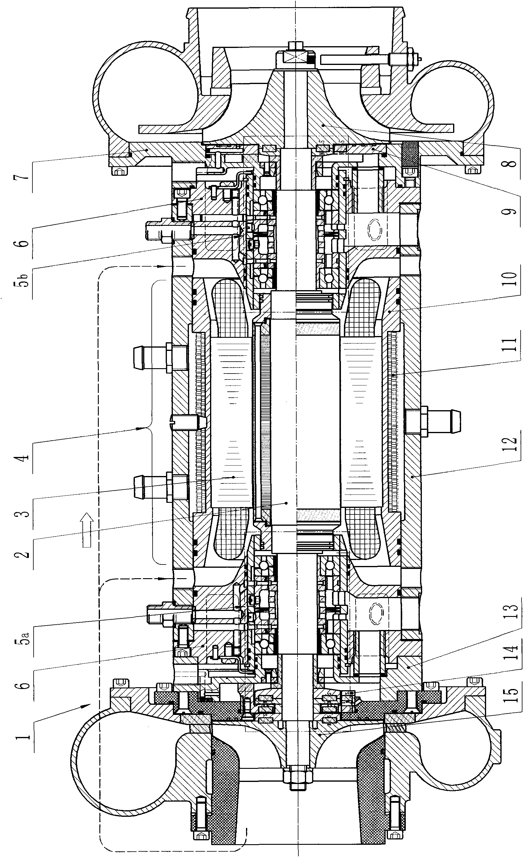
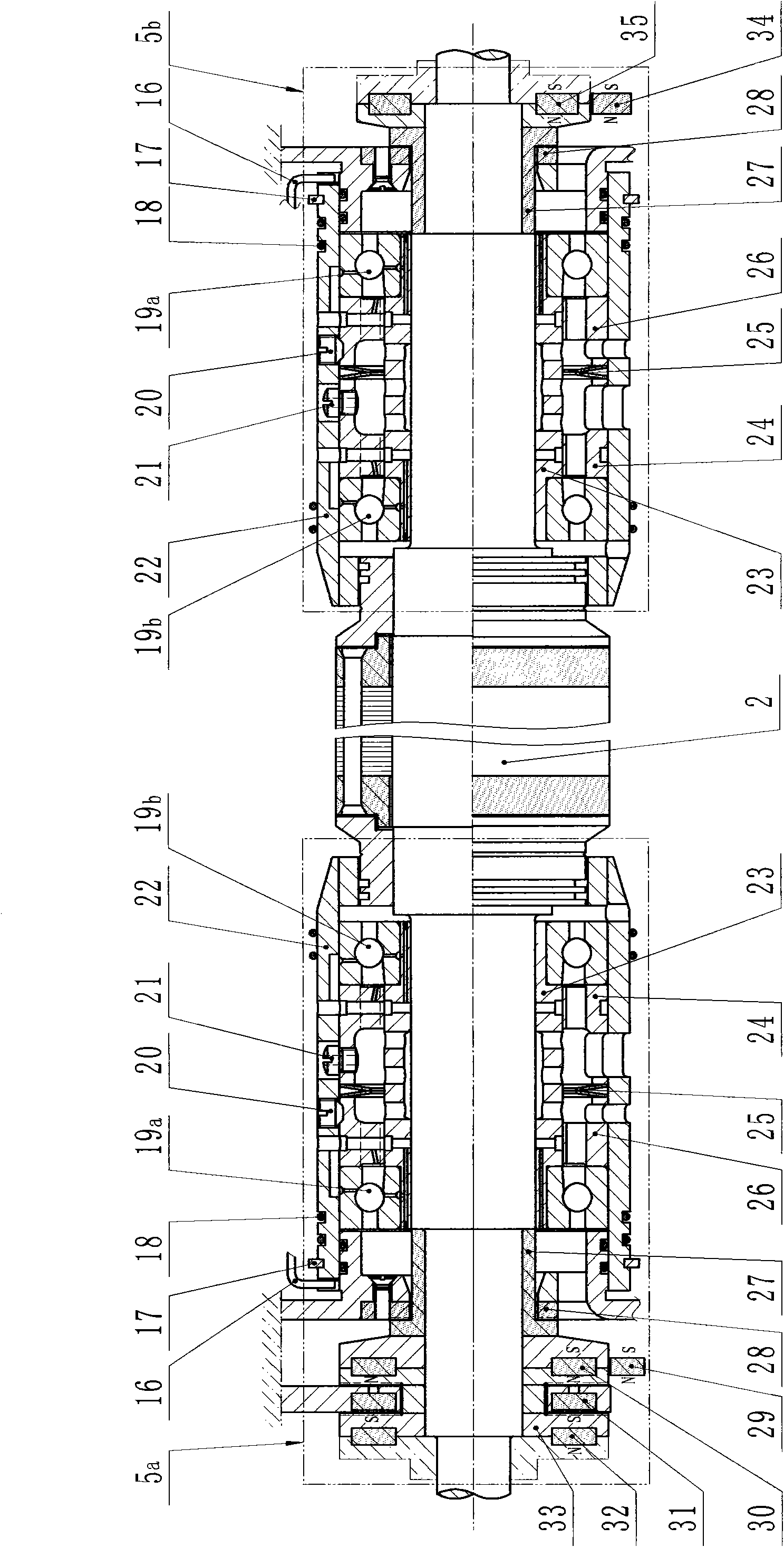
[0011] Specific embodiments of the present invention will be described below in conjunction with the accompanying drawings. figure 1 Shown is a front view of an air refrigerator 1 driven directly by an electric motor 4 comprising permanent magnet and roller sliding dual bearing motor rotor supports 5a and 5b of the present invention. figure 1 Among them, the air refrigerator 1 includes an electric motor 4 in the middle thereof. The motor 4 includes a rotor 2 and a stator 3 . Both sides of the rotor 2 are equipped with permanent magnet and roller sliding double bearing motor rotor supports 5a and 5b. The bearing seat 6 of the left end and the left water jacket cover 13 form the left cooling water jacket, and the bearing seat 6 of the right end and the right water jacket cover 7 form the right cooling water jacket. The stator casing 10 brazed with cooling fins 11 and the body 12 form the cooling water jacket of the stator 3 . The cooling impeller 15 and the compressor impelle...


PUM


Abstract

The invention relates to a rotor bearing used in a high-speed electric rotary machine. In the rotor bearing, a pair of angular contact ball bearings is nested at the two ends of a radial sliding bearing on the shaft neck of the two ends of a rotor, constant pressure pre-compression is adopted between the two ball bearings, the whole is embedded in a floating bushing; the outside end of the floating bushing is provided with a check ring and a check block for limiting the axial movement and rotation of the floating bushing, ensuring that the whole is in a semifloating state when installed in a bearing seat hole with a certain fit clearance and constructing a semifloating type rolling-sliding bearing. The two ends of the rotor are separately provided with a permanent magnet unloading bearing. When a high-power high-speed electric rotary machine using the rotor bearing of the invention is installed on a vehicle and operates in the rotate speed of more than 60000r/min, the operation of the system can be stable and reliable owning to the combined action of the semifloating rolling-sliding bearing and the permanent magnet unloading bearings.

Description

technical field [0001] The present invention relates to a rotor support for high-speed electric rotating machinery, in particular to a rotor support for air refrigerators, air compressors, etc. driven by large-capacity high-speed electric motors installed on vehicles, etc., wherein The rotor rotates at a high speed of, for example, not less than tens of thousands of revolutions per minute. Background technique [0002] One of the main technical issues in the design of high-power, high-speed high-speed motors (20kw, above 60000 / min) is bearing design. At present, for the bearing design of this kind of high-power, high-speed motor, it is generally considered to adopt the active magnetic bearing support method of the mixed support of electromagnetic bearing and rolling bearing, but the electronic control and manufacture of this magnetic bearing are complicated, expensive and reliable. low, and cannot be commercialized at present; the use of liquid sliding bearings is limited t...

Claims


Application Information

Patent Timeline
Patent Type & Authority Applications(China)
IPC IPC(8): H02K5/167H02K5/173H02K5/00
Inventor 何君伍怀秋何应明
Owner 何君
Why Eureka
Try Eureka