blender

A technology for mixers and mixing tanks, which is applied to mixer accessories, mixers, mixers with rotating containers, etc., which can solve the problems of time-consuming cleaning of mixers and easy residual impurities in the machine, and achieve the effect of improving efficiency

Active Publication Date: 2014-10-29
HERFELD GMBH & CO KG
View PDF4 Cites 0 Cited by
  • Summary
  • Abstract
  • Description
  • Claims
  • Application Information

AI Technical Summary

Problems solved by technology

[0007] When the production raw materials of the same mixer change, that is, when the object to be cooled changes, the cleaning of the mixer is extremely time-consuming. The reason for the time-consuming is that the geometric structure of the mixer determines that impurities are easy to remain inside the machine, and the mixer used for mixing must be cleaned

Method used


Image

  • blender
  • blender
  • blender

Examples


Embodiment Construction

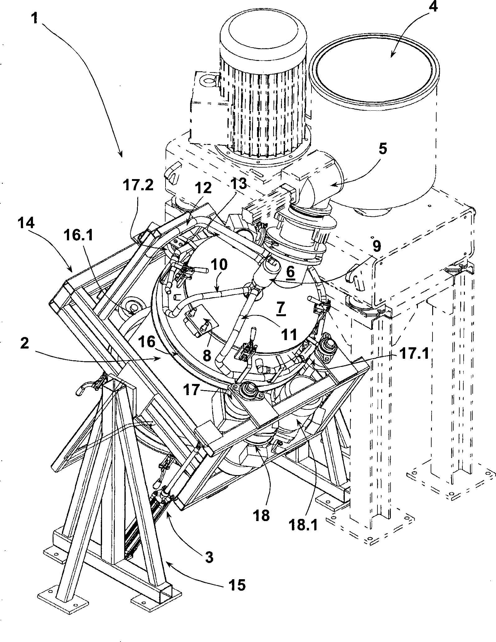
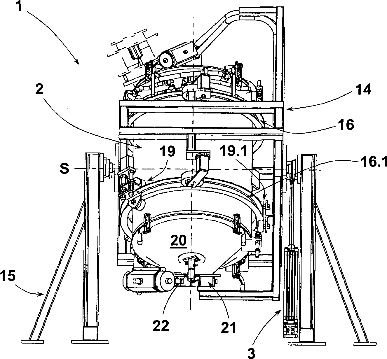
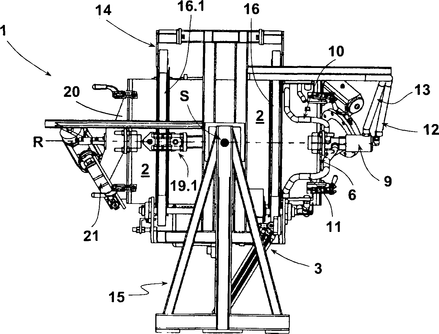
[0047] The present invention is designed as a cooling mixer 1, which contains a mixing bucket 2, which surrounds a horizontal swing axis S by adjusting a cylinder 3 (compare to image 3 ) to swing. exist figure 1 , shows a schematic diagram of the cooling mixer 1 and the main mixing tank 2, figure 1 is a schematic diagram of the feeding state. The feed state is also the static state of the adjustment cylinder 3. figure 1 The dotted line part next to the middle cooling mixer 1 is the heating mixer 4, and the outlet of the heating mixer 4 is also the feed inlet 5 of the cooling mixer 1, and the top of the mixing bucket 2 is connected with the feed inlet 5 by a pneumatic movable coupling. The hinged barrel is realized through the feeding hub 6. This connection method establishes a connection path from the feeding port 5 to the mixing drum 2. The inside of the feeding port 5 is provided with a baffle structure, and the baffle can be opened and closed to play a role. For the fu...


PUM


Abstract

The cooling mixer (1) has a mixture container (2) for admission of a mixture which is cooled. The container has cooling agent channels with its surface partly in contact with the solid particles. The container is supported around the axle breaking through two faces (7) in pivoted manner. A motor drive (17,18,18.1) is provided as rolling over unit for the rotation of the container.

Description

technical field [0001] The invention provides a mixer capable of adjusting temperature. The mixer can cool the solid mixture. The mixer includes a mixing bucket for containing the mixture. The mixing bucket at least ensures that the solid particle raw material that needs to be cooled is in effective contact with the coolant channel for temperature regulation, and is mainly powered by the motor of the mixer. , to work as an auxiliary temperature-regulating medium, and to stir the mixture in the mixing tank. Background technique [0002] Mixers of the type mentioned above are now in use and are usually used to cool mixtures that have been homogenized in other mixers before. So this type of mixer is usually also called cooling mixer. And in general, according to the complete process flow, there is usually a heating and stirring process before using the cooling mixer. The mixture is heated in the heating and stirring process and must be cooled in the subsequent process accord...

Claims


Application Information

Patent Timeline
Patent Type & Authority Patents(China)
IPC IPC(8): B01F9/04B01F15/06B01F3/18B01F29/62B01F23/70B01F29/63
CPCB01F2015/061B01F3/18B01F2215/0049F28D7/106F28D2021/0052B01F2009/0092B01F3/20B01F15/065F28D11/02F28F1/02F28D2021/0045B01F3/2078B29B7/50B01F9/06F28F2215/06B01F23/70B01F23/711B01F23/60B01F29/40221B01F29/63B01F2035/98B01F35/92B01F2101/2805
Inventor 乌尔里希·托勒沃夫冈·鲁贝格马西亚斯·赫费尔德
Owner HERFELD GMBH & CO KG
Why Eureka
Try Eureka