
Benefication technology of extra poor hematite

A technology of iron ore and process, which is applied in the field of sorting technology of extremely poor hematite ore, can solve the problems of increasing the processing capacity of regrinding operations, low grade of selection, poor sorting index, etc., and achieves reduction of investment cost and operation cost, reduce the amount of regrinding, and improve the effect of selecting other indicators

Active Publication Date: 2010-12-29
鞍钢集团矿业设计研究院有限公司
View PDF0 Cites 30 Cited by
  • Summary
  • Abstract
  • Description
  • Claims
  • Application Information

AI Technical Summary

Problems solved by technology

When this process handles extremely poor low-grade ores, since the raw ore (one-point overflow) is directly fed into the coarse and fine classification operation without weak magnetic and strong magnetic separation, the selected grade of the gravity separation operation (two-stage spiral chute) is low, and the processing However, some experiments have shown that if the raw ore (Yifenyi) is separated by weak magnetic and strong magnetic separation and then coarsely classified, the fine particles will be separated by reverse flotation. , and the raw ore (yifenyi) is coarsely and subdivided first, and the fine-grained part is separated by weak and strong magnetic separation, and then the mixed magnetic concentrate is separated by reverse flotation. The ore grade of the flotation operation is similar, but the separation index poor

Method used


Image

  • Benefication technology of extra poor hematite
  • Benefication technology of extra poor hematite

Examples


Embodiment Construction

[0025] The specific embodiments of the present invention are described below in conjunction with the drawings.

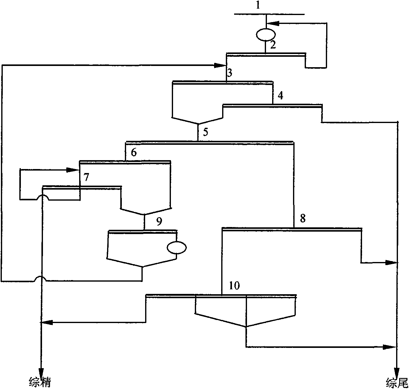
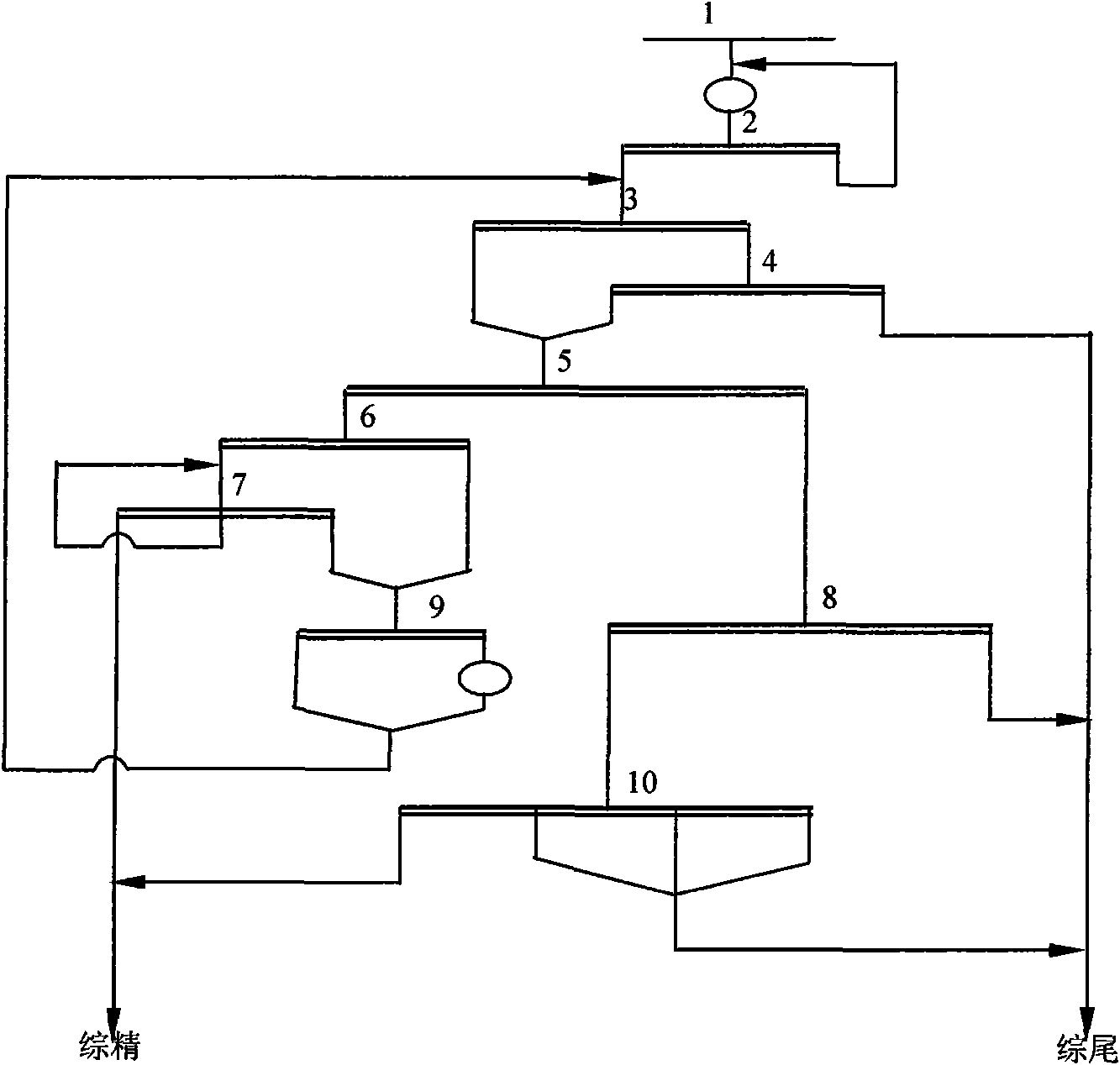
[0026] Such as figure 1 As shown, the separation process of extremely lean hematite ore of the present invention is characterized in that it includes the following steps:

[0027] 1) Raw ore 1 is fed into a ball mill for grinding,

[0028] 2) The ground products of the primary ball mill are fed into the primary spiral classifier for primary classification. The closed-circuit grinding system composed of the primary ball mill and the spiral classifier 2.

[0029] 3) Feed the overflow of the primary spiral classifier 2 with a concentration of 45-50%, a particle size of -200 mesh, a content of 60-70%, and a grade of less than 15-25% into the weak magnetic separator 3. The weak magnetic tails separated by the separator 3 are concentrated to a concentration of 35-45%. The weak magnetic tails separated by the weak magnetic separator are concentrated and fed to the strong magnetic...


PUM


Abstract

The invention relates to a benefication technology of extra poor hematite, which is characterized by comprising the following steps: feeding a raw ore in a closed circuit grinding system composed of a primary ball mill and a spiral classifying mechanism, feeding in a weak magnetic machine for benefication after primary classification and overflow, feeding the weak magnetic tailing in a strong magnetic machine, feeding a mixed magnetic concentrate composed of a weak magnetic concentrate and a strong magnetic concentrate in a spiral chute, obtaining a selected spiral concentrate as a coarse grain concentrate after the coarse grains are subjected to two-stage spiral chute benefication, performing self-circulation on the middling in the selected spiral chute, forming the middling by a roughly selected spiral tailing and a selected spiral tailing, feeding the middling in an open circuit grinding system composed of secondary classifying and secondary grinding for re-grinding, returning to the weak magnetic machine after re-grinding, feeding the overflow of a swirler after benefication of a centrifuge into a table for benefication, merging a table middling, table slurry and a table tailing into a table tailing, merging the strong magnetic tailing, a centrifugal tailing and a table tailing as a final tailing, and merging the selected spiral chute concentrate and the table concentrate into a final concentrate. The invention can improve the milling grade of follow-up operations of the extra poor hematite, reduce the re-grinding amount of the middlings, and is favor of acquiring better beneficiation indexes.

Description

Technical field [0001] The invention belongs to the technical field of hematite ore beneficiation in ferrous metal beneficiation, in particular to a separation process of extremely lean hematite ore. Background technique [0002] At present, ferrous metal beneficiation generally adopts two technological processes: "stage grinding, coarse subdivision, heavy-magnetic-anion reverse flotation" process and "stage grinding, magnetic separation-fine screen regrind" process. In recent years, driven by the rapid development of the iron and steel industry and the increasing demand for iron ore concentrates, iron ore beneficiation has shown an unprecedented development situation. Old concentrators have been expanded and newly-built concentrators have been put into operation, thus accelerating iron ore processing. The speed of the development and utilization of ore resources, it is currently very difficult to find better quality iron ore resources. Therefore, the research and development and...

Claims


Application Information

Patent Timeline
IPC IPC(8): B03B7/00
Inventor 杨晓峰宋均利刘双安张丛香
Owner 鞍钢集团矿业设计研究院有限公司
Learn More