Eureka AIR delivers breakthrough ideas for toughest innovation challenges, trusted by R&D personnel around the world.

Telescopic arm type lorry-mounted crane

A truck-mounted crane and telescopic boom technology, applied in cranes and other directions, can solve the problems of increasing the height of the whole machine, large luffing thrust, and increasing the weight of the whole machine, so as to ensure waterproof sealing, reduce the height of the whole machine, and reduce the whole machine. The effect of weight

Inactive Publication Date: 2010-12-29
CHANGZHI QINGHUA MACHINERY FACTORY
View PDF0 Cites 10 Cited by
  • Summary
  • Abstract
  • Description
  • Claims
  • Application Information

AI Technical Summary

Problems solved by technology

At the same time, the operating environment of special vehicles is complex, which requires that the telescopic boom truck mounted cranes installed on them have good waterproof and sealing properties.
[0003] The traditional telescopic boom truck-mounted crane adopts a split-type winch lifting mechanism and installs it inside the boom or the column, resulting in an increase in the cross section of the boom or the height of the column, resulting in heavier weight and larger dimensions. In particular, the height is high, and at the same time, it also brings difficulties to the waterproof sealing of the boom or column; the luffing cylinder of the traditional telescopic boom truck-mounted crane adopts a rear-mounted arrangement, which requires a large luffing thrust, which requires a large diameter hydraulic cylinder, thus increasing the weight of the whole machine; after the boom of a traditional telescopic boom truck-mounted crane is connected to the column, when the boom elevation angle is zero degrees, the highest ridge point of the hexagonal cross-section of the boom is higher than the highest point of the column , increasing the height of the machine

Method used


Image

  • Telescopic arm type lorry-mounted crane

Examples


Embodiment Construction

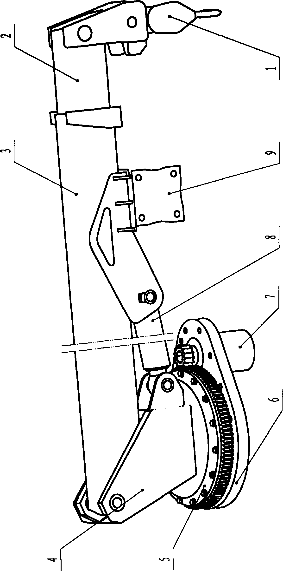
[0015] Such as figure 1 As shown, the telescopic arm type truck-mounted crane of the present invention includes: a hook 1, a telescopic arm 2, a boom 3, a column 4, a slewing bearing 5, a slewing bearing base assembly 6, an integral slewing device 7, a luffing cylinder 8 and Integral hoist 9; the integral slewing device 7 is fixed on the front end of the slewing bearing base assembly 6, the slewing bearing 5 is fixed on the rear end of the slewing bearing base assembly 6, the planetary gear on the integral slewing device 7 and the slewing bearing 5 The large gears are meshed together, the column 4 is fixed on the top of the slewing bearing 5, the top of the column 4 is connected with the boom 3, the front end of the column 4 is hinged with the cylinder barrel of the luffing cylinder 8, and the luffing cylinder 8 The piston rod and the middle part of the boom 3 are hinged together. The integral winch 9 is set under the boom 3 and fixed at the front end of the luffing cylinder 8...


PUM


Abstract

The invention relates to a telescopic arm type lorry-mounted crane which belongs to the technical field of telescopic arm type lorry-mounted crane. Compared with the existing telescopic arm type lorry-mounted crane, the weight and size of the entire machine are reduced and the height and manufacturing cost of the entire machine are lowered. In the crane of the invention, an integral slewing device is fixed on the front end of the base assembly of a slewing bearing; the slewing bearing is fixed on the back end of the base assembly of the slewing bearing; an upright is fixed on the slewing bearing; the top of the upright is connected with a suspension arm; the front end of the upright is hinged with the cylinder barrel of a derricking cylinder; the piston rod of the derricking cylinder is hinged with the middle part of the suspension arm; an integral winch is arranged below the suspension arm; a telescopic arm is arranged in the suspension arm; the lower part of the front end of the telescopic arm is provided with a hook; and the upright has a groove-shaped box structure, and the inclination of the slope of the box on the upright is matched with the inclination of a lower slope at the tail end of the suspension arm. The crane of the invention can be widely used to lift weights in various projects.

Description

technical field [0001] The telescopic boom truck-mounted crane of the invention belongs to the technical field of telescopic boom truck-mounted cranes. Background technique [0002] The telescopic boom truck-mounted crane is installed on a special vehicle. Due to the weight and height constraints of the vehicle, it is required that the telescopic boom truck-mounted crane installed on it is light in weight, compact in size, and especially low in height. At the same time, the operating environment of special vehicles is complex, which requires that the telescopic boom truck-mounted cranes installed on them have good waterproof and sealing properties. [0003] The traditional telescopic boom truck-mounted crane adopts a split-type winch lifting mechanism and installs it inside the boom or the column, resulting in an increase in the cross section of the boom or the height of the column, resulting in heavier weight and larger dimensions. In particular, the height is high, and at...

Claims


Application Information

Patent Timeline
Patent Type & Authority Applications(China)
IPC IPC(8): B66C23/687B66C23/36
Inventor 郭金龙孙治国李志青汤志远王乐有许燕强孙晓峰吴庆亮赵振峰许佩霞
Owner CHANGZHI QINGHUA MACHINERY FACTORY
Why Eureka
Eureka Blog
Learn More