Energy-saving water heater

A technology for energy-saving water heaters and waterways, applied in water heaters, fluid heaters, lighting and heating equipment, etc., can solve the problems of complex control mechanisms, waste of water resources, waste of time, etc., to achieve small size, prolong service life, and use handy effect

Inactive Publication Date: 2012-08-08
钟国芳
View PDF1 Cites 0 Cited by
  • Summary
  • Abstract
  • Description
  • Claims
  • Application Information

AI Technical Summary

Problems solved by technology

[0002] Existing water heaters, such as electric water heaters, gas water heaters, and solar water heaters, have large capacity, large volume, and difficult maintenance. In addition, because the installation location and the use location are not in the same place, hot water will not flow out immediately when used, and a lot of water needs to be installed. The cold water in the long section of the water pipe is released, and there will be a section of hot water in the water pipe after use, which wastes water resources, energy and time
[0003] Patent No. 200520117067.X "A Fast Electric Water Faucet with Two-way Water Inlet" also provides an electric water faucet with two-way water inlet, fast electric heating, time-saving, energy-saving, water-saving and solar water heaters. When the power is not connected, This faucet can still be used as an ordinary faucet to provide cold water, but it adopts a double water inlet structure. When using it, two cold and hot water inlet pipes need to be installed, and the cold and hot water inlet pipes need to be connected with the cold and hot water on the two-way ceramic valve core. It can only be used when the water port is connected, and its control mechanism is more complicated. There is a manual switch between the control handle and the two-way ceramic valve core. The manual switch, water pressure switch, and electric heater are connected in series. , Electromagnetic coil connection of the relay

Method used


Image

  • Energy-saving water heater
  • Energy-saving water heater
  • Energy-saving water heater

Examples


Embodiment Construction

[0017] Embodiments of the present invention will be further described below in conjunction with the accompanying drawings.

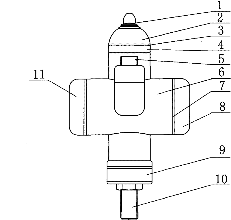
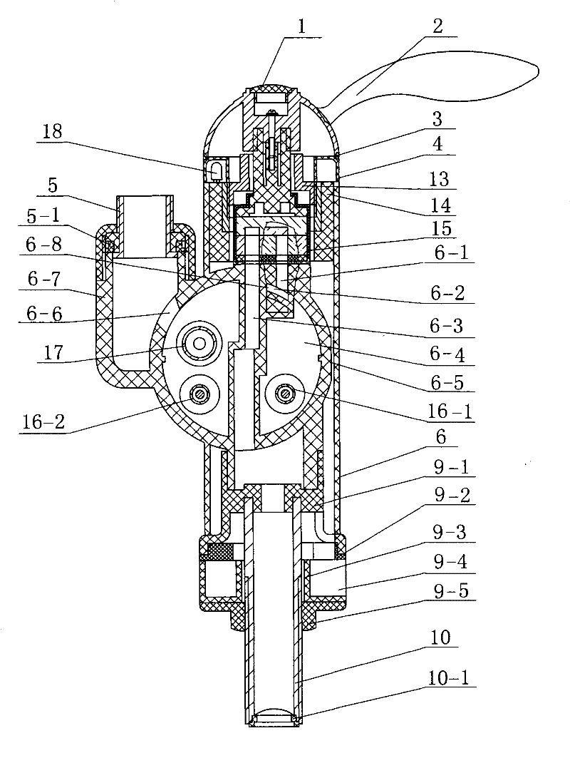
[0018] The housing 6 is cross-shaped, and the lower end is connected to the water inlet pipe 10 with the filter screen 10-1 through the connector 9. The connector 9 is composed of a washer 9-3 with a gap 9-4, a rubber ring 9-2 with a gap, and a nut 9 -5 and the joint 9-1 that is fixed with water inlet pipe 10 are connected as a whole, and is fixed on the water inlet pipe 10 with nut 9-5, as image 3 shown.

[0019] The transverse cavity in the middle of the shell is divided into a left cavity and a right cavity with no communication between the left and right by the through holes, grooves, gaps, and connecting column partitions 6-4 on the upper side. The left cavity is the control cavity where the circuit board is installed. 19, a water pressure switch 21 is installed in the groove, such as Figure 6 As shown, the water pressure switch 21 is inserted i...


PUM


Abstract

The invention relates to an energy-saving water heater. The shell is injection-molded into an integral body and separated into a left control chamber and a right heating chamber by a partition, wherein a wiring board in the control chambers is connected with an electrothermal tube switch which is composed of upper and lower contact spring tabs and a hydraulic pressure switch; the hydraulic pressure switch is formed by inserting an elastic cup, which is provided with an expansion link and installed on the partition, into a cover with a through hole in the middle; the inner wall of the heating chamber is provided with a transverse water inlet duct; the side wall of the transverse water inlet duct is provided with a cold water outlet which is tangential to the inner wall of the heating chamber; a ceramic valve core and a handle are connected to constitute a rotatable integral body; and the ceramic valve core is formed by connecting movable and fixed chips in a sleeve, a bottom plate, a seal ring and a rotary handle. The invention has the advantages of simple and compact structure, small size, easy assembly and maintenance, and convenient and flexible operation. The electric heater isautomatically connected by using the hydraulic pressure switch, only one water inlet tube is required, the user can use the water heat without adding accessories, and cold water can become hot water within 3 seconds; no bubbles are produced in the heating chamber; and thus, the invention greatly enhances the thermal efficiency and the effluent rate and prolongs the service life of the electrothermal tube.

Description

technical field [0001] The invention relates to an electric water heater, in particular to an energy-saving water heater that is instant on and heats quickly. Background technique [0002] Existing water heaters, such as electric water heaters, gas water heaters, and solar water heaters, have large capacity, large volume, and difficult maintenance. In addition, because the installation location and the use location are not in the same place, hot water will not flow out immediately when used, and a lot of water needs to be installed. The cold water in the long section of the water pipe is let off, and a section of hot water will be left in the water pipe after use, which not only wastes water resources but also wastes energy and time. [0003] Patent No. 200520117067.X "A Fast Electric Water Faucet with Two-way Water Inlet" also provides an electric water faucet with two-way water inlet, fast electric heating, time-saving, energy-saving, water-saving and solar water heaters. ...

Claims


Application Information

Patent Timeline
Patent Type & Authority Patents(China)
IPC IPC(8): F24H1/00F24H9/20
Inventor 钟国芳
Owner 钟国芳
Why Eureka
Try Eureka