Flat pipe and fin structures of parallel flow heat exchanger

An exchanger and flat tube technology, applied in the field of components of parallel flow heat exchangers, can solve the problems of high product defect rate, increased manufacturing cost, unreliable welding, etc., and achieves convenient processing and manufacturing, stable heat exchange efficiency, and improved excellent rate effect

Inactive Publication Date: 2010-12-29
浙江金宸三普换热器有限公司
View PDF7 Cites 6 Cited by
  • Summary
  • Abstract
  • Description
  • Claims
  • Application Information

AI Technical Summary

Problems solved by technology

However, because the fins and the flat tubes only rely on the friction of contact, some fins will often fall off during or after welding, especially for some large heat exchangers, and then go to fix or secondary welding, etc. There will be defects such as unreliable welding and high welding plugging of the product, and the defective rate of the product is relatively high, which also increases the manufacturing cost accordingly
In addition, after the heat exchanger has been used for many years, the solder joints between the fins and the flat tubes are corroded or cracked by vibration, which will also cause the fins to fall off.
These will reduce the heat transfer efficiency of the entire heat exchanger

Method used


Image

  • Flat pipe and fin structures of parallel flow heat exchanger
  • Flat pipe and fin structures of parallel flow heat exchanger
  • Flat pipe and fin structures of parallel flow heat exchanger

Examples


Embodiment

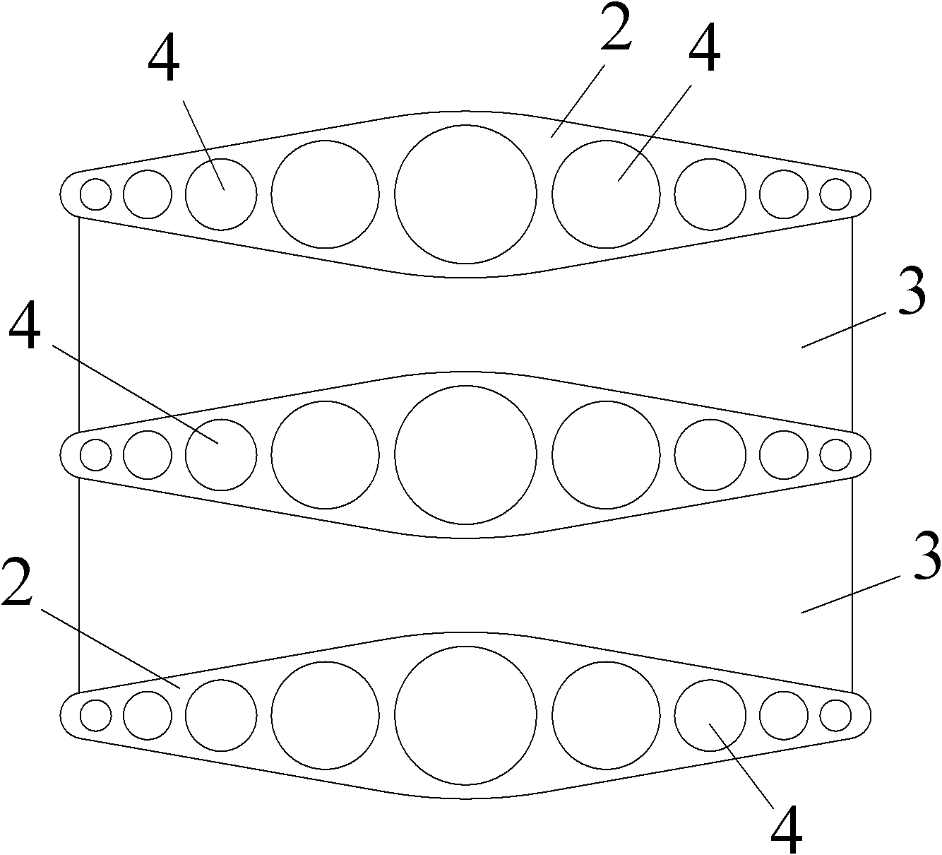
[0010] Example: see figure 1 and figure 2 , the heat exchanger of the present invention includes several flat tubes 2 inserted on the headers 1 at both ends, fins 3 are arranged between adjacent flat tubes 2, and the microchannels 4 on the flat tubes 2 communicate with the headers 1 at both ends. . Wherein, both sides of the flat tube 2 are raised in the longitudinal middle, and correspondingly, the fins 3 are concave in the longitudinal middle of both sides, which can prevent the fins from falling off due to lateral movement. Preferably, the raised parts in the longitudinal middle of both sides of the flat tube 2 have a smooth transition, and correspondingly the concave structures in the longitudinal middle of both sides of the fin 3 also have a smooth transition, which facilitates the processing and manufacturing of components.

[0011] In the present invention, the flat tube is designed as a raised structure in the longitudinal middle of both sides, and the corresponding...


PUM


Abstract

The invention discloses flat pipe and fin structures of a parallel flow heat exchanger, which comprise a plurality of flat pipes inserted on header pipes on two ends of the heat exchanger, fins are arranged between adjacent flat pipes, and micro-channels on the flat pipes are communicated with the header pipes on the two ends of the heat exchanger; and longitudinal middle parts at two sides of each flat pipe protrude, and correspondingly each fin is of a structure in which the longitudinal middle parts at two sides are sunken, thus avoiding the fins moving transversely to result in falling-off. Preferably, the protruding parts of the longitudinal middle parts at the two sides of each flat pipe are subjected to smoothing transition, and correspondingly the sunken structure of the longitudinal middle parts at the two sides of each fin is also subjected to smoothing transition, thus facilitating processing and manufacturing of components. After assembly brazing is completed, the fins can remain stationary transversely, thus effectively avoiding the fin moving transversely to result in falling-off; and after long-term service, the fins do not drop even though welding spots between the fins and the flat pipes are corroded or cracked owing to vibration and the like, thus achieving relatively stable heat exchange efficiency of the heat exchanger, facilitating overall processing and manufacturing, and improving excellence rate of assembly processing of the heat exchanger.

Description

technical field [0001] The invention relates to a component of a parallel flow heat exchanger, in particular to a flat tube and fin structure of the parallel flow heat exchanger. Background technique [0002] Parallel flow heat exchanger is a device that realizes heat transfer between cold and hot fluids, and is widely used in HVAC and other fields. A parallel-flow heat exchanger generally includes two headers parallel to each other, a number of substantially parallel flat tubes for heat dissipation are arranged between the two headers, and fins for heat dissipation are brazed between adjacent flat tubes. The fins are made of aluminum sheet material, mostly in a corrugated structure, and the outer surfaces of the crests and troughs are set against the upper and lower sides of the flat tube, and finally fixed by brazing. However, because the fins and the flat tubes only rely on the friction of contact, some fins will often fall off during or after welding, especially for som...

Claims


Application Information

Patent Timeline
Patent Type & Authority Applications(China)
IPC IPC(8): F28F1/02F28F1/26F25B39/00
Inventor 何金汉
Owner 浙江金宸三普换热器有限公司
Why Eureka
Try Eureka