Quadratic element optical measuring device capable of continuously conveying objects to be measured

An optical measurement and quadratic element technology, used in measurement devices, optical devices, instruments, etc., can solve the problems of large volume, rapid mass production, detection bottlenecks, and complex designs.

Active Publication Date: 2010-12-29
MACHVISION INC
View PDF0 Cites 7 Cited by
  • Summary
  • Abstract
  • Description
  • Claims
  • Application Information

AI Technical Summary

Problems solved by technology

[0006] The biggest problem with the aforementioned optical measurement device 10 is that the objects to be measured 80 need to be fixed on the carrying fixed platform 14 one by one, and then removed from the carrying fixed platform 14 one by one after measurement, so the time for waiting for measurement or preparation operations will be delayed. long, other conventional optical measurement devices suffer from similar difficulties

Method used


Image

  • Quadratic element optical measuring device capable of continuously conveying objects to be measured
  • Quadratic element optical measuring device capable of continuously conveying objects to be measured
  • Quadratic element optical measuring device capable of continuously conveying objects to be measured

Examples


Embodiment Construction

[0027] The making and using of the presently preferred embodiments of the invention are discussed in detail below. It should be understood, however, that the present invention provides many applicable means and can be embodied in a wide variety of specific situations. The specific examples discussed are merely illustrative of specific ways to make and use the invention, and do not limit the scope of the invention.

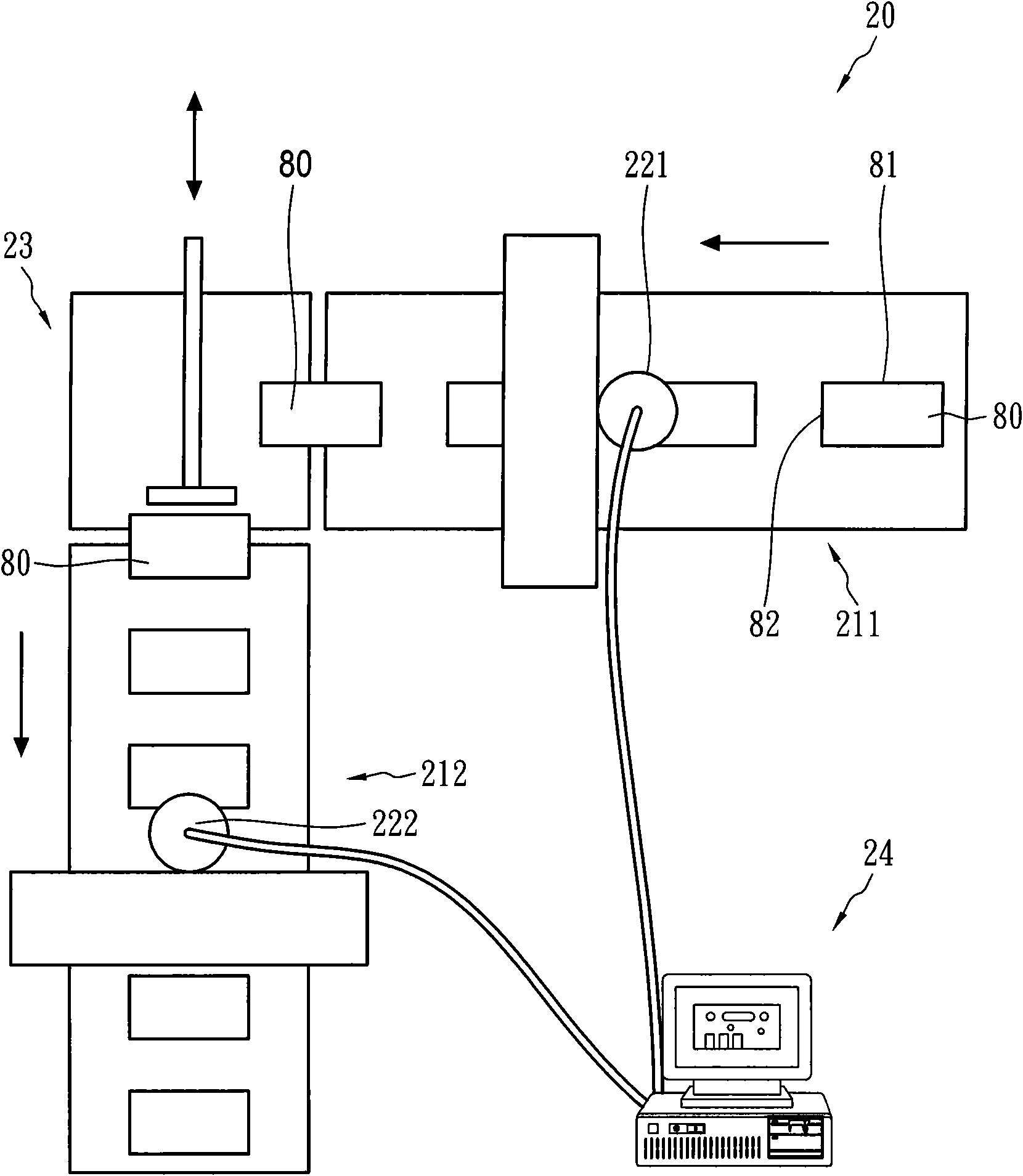
[0028] figure 2 It is a schematic diagram of a two-dimensional optical measuring device capable of continuously conveying objects to be measured according to an embodiment of the present invention. Such as figure 2 , the second-dimensional optical measuring device 20 of the present invention can continuously measure a plurality of objects to be measured 80 that are conveyed, and it includes two image scanners (221, 222), at least two conveyors (211, 212), a steering conveyor Mechanism 23 and an image processor 24 . The two image scanners (221, 222) are respec...


PUM


Abstract

The invention discloses a quadratic element optical measuring device capable of continuously conveying objects to be measured, which can be used for continuously measuring a plurality of conveyed objects to be measured. The quadratic element optical measuring device comprises two image scanners, at least two conveyers, one steering transport mechanism and an image processor. The two image scanners are fixed at positions through which conveying belts of the at least two conveyors pass respectively, and retrieve images respectively along two approximately mutually vertical size directions on each object to be measured. The steering conveying transport mechanism steers the plurality of the objects to be measured respectively, and continuously conveys the objects to be measured between the at least two conveyers. The image processor receives image data of the two image scanners, and synthesizes the image data to obtain a two-dimensional image of each object to be measured so as to execute a geometric dimension measurement, thereby obtaining the effects of reduced cost, high unit time output and accurate measurement.

Description

technical field [0001] The present invention relates to a secondary optical measuring device capable of continuously conveying objects to be measured, in particular to a secondary optical measuring device capable of continuously conveying and measuring objects to be measured. Background technique [0002] Printed circuit boards are the main components of electronics, computers, and communications products. In order to adapt to the light, thin, short, and small product characteristics in the consumer market, and under the catalysis of high-density and high-reliability requirements, advanced printed circuit boards In the current development trend, blind hole (via) and buried hole technologies are mostly used. This kind of printed circuit board with blind holes and buried holes uses blind holes to connect the wiring boards of the inner layers to the wiring on the surface. It does not need to penetrate the entire board and waste the layout space of other layers of wiring boards....

Claims


Application Information

Patent Timeline
IPC IPC(8): G01B11/00G01B11/10G01B11/12G01B11/14
Inventor 汪光夏刘旭仁王舜民邱诗彰王荣发许裕騄陈振庆黄建荣蔡瑞彬
Owner MACHVISION INC
Why Eureka
Try Eureka