Piston heat load test device and method

A technology of experimental device and heating device, applied in the direction of measuring device, instrument, scientific instrument, etc., can solve the problems of uncontrollable heating area, long experimental period, inaccurate temperature control, etc. good control effect

Inactive Publication Date: 2010-12-29
INST OF MECHANICS - CHINESE ACAD OF SCI
View PDF0 Cites 25 Cited by
  • Summary
  • Abstract
  • Description
  • Claims
  • Application Information

AI Technical Summary

Problems solved by technology

[0005] The purpose of the present invention is to overcome the shortcomings of the above-mentioned prior art, such as long experimental period, uncontrollable heating area, and inaccurate temperature control, thereby providing a short experimental period, controllable heating area, more accurate temperature control, and an overall test of the piston. Laser Induced Piston Thermal Fatigue Experimental Device

Method used


Image

  • Piston heat load test device and method
  • Piston heat load test device and method
  • Piston heat load test device and method

Examples


Embodiment Construction

[0031] The present invention will be further described in detail in specific embodiments below in conjunction with the accompanying drawings. It should be understood that these embodiments are only used to illustrate the basic principle of the present invention, rather than limit the present invention.

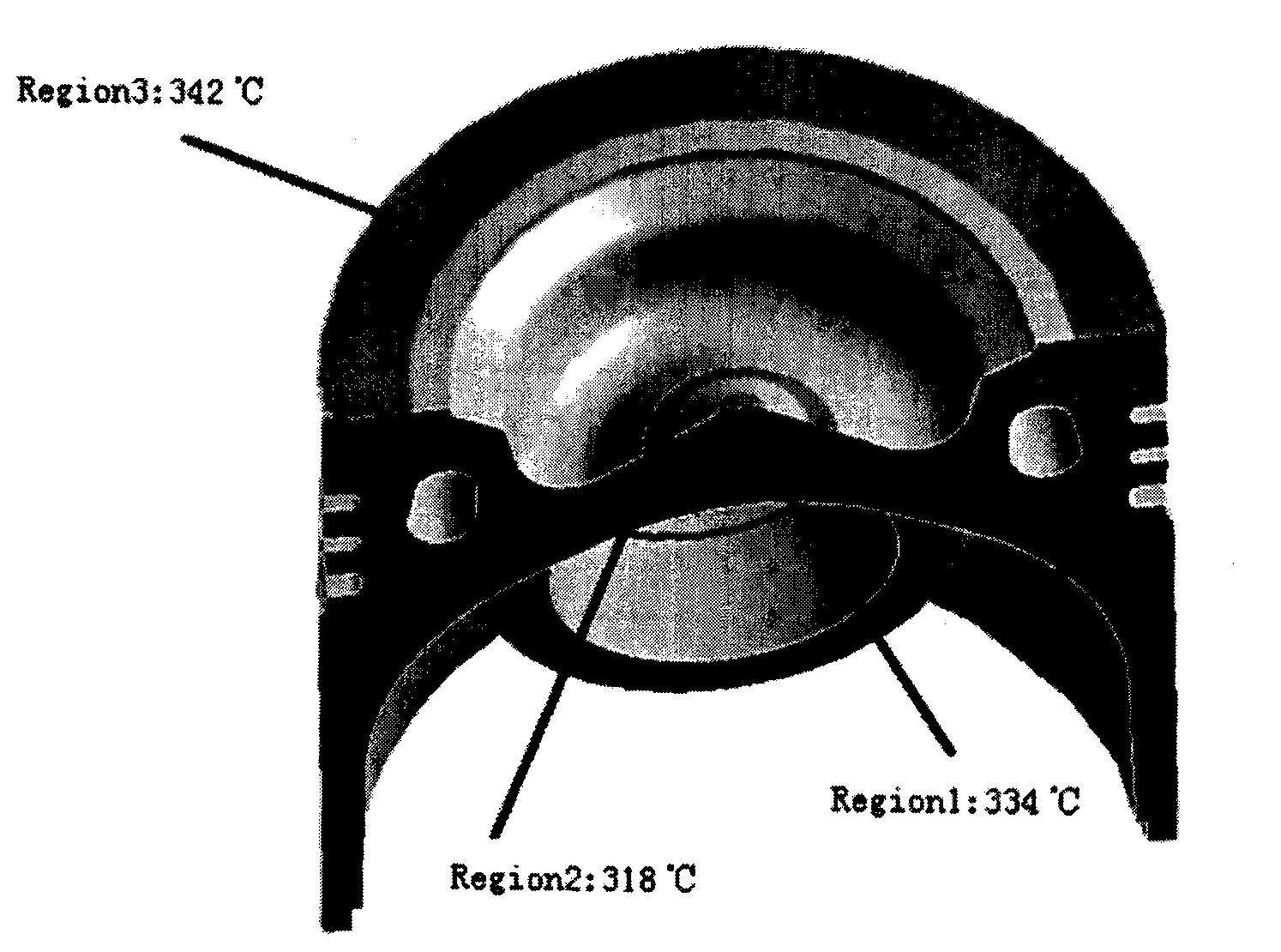
[0032] First, refer to figure 2 , figure 2 A cross-sectional diagram of the piston is shown as an example to show the temperature distribution in different regions under real working conditions. As shown in the background technology, due to the fact that the temperature inside the piston is not consistent under real working conditions, therefore, in order to set up an experimental system capable of simulating real working conditions, the present invention attempts to establish a set of test systems that can control the temperature of the piston. Carry out thermal load test as a whole. In one embodiment of the present invention, the temperature distribution inside the pist...


PUM


Abstract

The invention discloses a piston heat load test device with a laser as a heat source, and a piston heat load test method. The device comprises a bracket, a control device, a heating device, a temperature sensing device, a monitoring device and a cooling device, wherein the heating device consists of a laser device and a beam shaper which changes a laser beam emitted by the laser device into a laser beam with a plurality of concentric ring-shaped spots and projects the laser beam onto a piston surface vertically. The method comprises the following steps of: firstly, optimizing a laser energy distribution ratio of areas on the piston surface according to the temperature field distribution of a piston under an actual working condition; secondly, designing an optical conversion plate according to the energy distribution ratio; thirdly, converting an incident beam into a concentric ring beam which meets the requirement on the laser energy distribution ratio of the areas; and fourthly, simulating the temperature field distribution law of the piston under the actual working condition by loading the beam on the piston. The device and the method can simulate the temperature field distribution on the piston surface under the actual working condition and have the advantages of short experiment period, high reliability and high controllability.

Description

technical field [0001] The invention relates to a thermal fatigue test device, in particular to a piston thermal fatigue test device which designs an optical conversion sheet according to the characteristics of the temperature field under the actual working condition of the piston and uses laser as a heat source. Background technique [0002] At present, for the known technologies of piston thermal fatigue testing devices, many research institutions such as Zhejiang University have successively established thermal fatigue simulations using electromagnetic induction coils, quartz lamps, resistance heaters or gas flame injectors as heating methods. experiment platform. In general, the disadvantages of this type of testing device are: the experiment cycle is relatively long, and the heating area is uncontrollable. [0003] In the known technology, adopt laser to carry out the thermal fatigue test device of material sample, as document 1, M.Kutsuna, S.Fujita, Y.Sugita, et al.Th...

Claims


Application Information

Patent Timeline
Patent Type & Authority Applications(China)
IPC IPC(8): G01N3/60
Inventor 虞钢张永杰郑彩云宁伟键何秀丽
Owner INST OF MECHANICS - CHINESE ACAD OF SCI
Why Eureka
Try Eureka