
Micro-mirror display

A display and micromirror technology, applied in the direction of instruments, optical components, optics, etc., can solve the problems of complex optical path design and beam control, and achieve the effect of simple structure and simple optical path design

Active Publication Date: 2010-12-29
XIAN YISHEN OPTOELECTRONICS TECH CO LTD
View PDF7 Cites 2 Cited by
  • Summary
  • Abstract
  • Description
  • Claims
  • Application Information

AI Technical Summary

Problems solved by technology

[0004] The embodiment of the present invention provides a micromirror display, which is used to solve the problems of complex optical path design and control of light beams of different colors when DMD is used to process multiple colors in the prior art

Method used


Image

  • Micro-mirror display
  • Micro-mirror display
  • Micro-mirror display

Examples


Embodiment Construction

[0022] In order to make the purpose, technical solutions and advantages of the embodiments of the present invention clearer, the technical solutions in the embodiments of the present invention will be clearly and completely described below in conjunction with the drawings in the embodiments of the present invention. Obviously, the described embodiments It is a part of embodiments of the present invention, but not all embodiments. Based on the embodiments of the present invention, all other embodiments obtained by persons of ordinary skill in the art without creative efforts fall within the protection scope of the present invention.

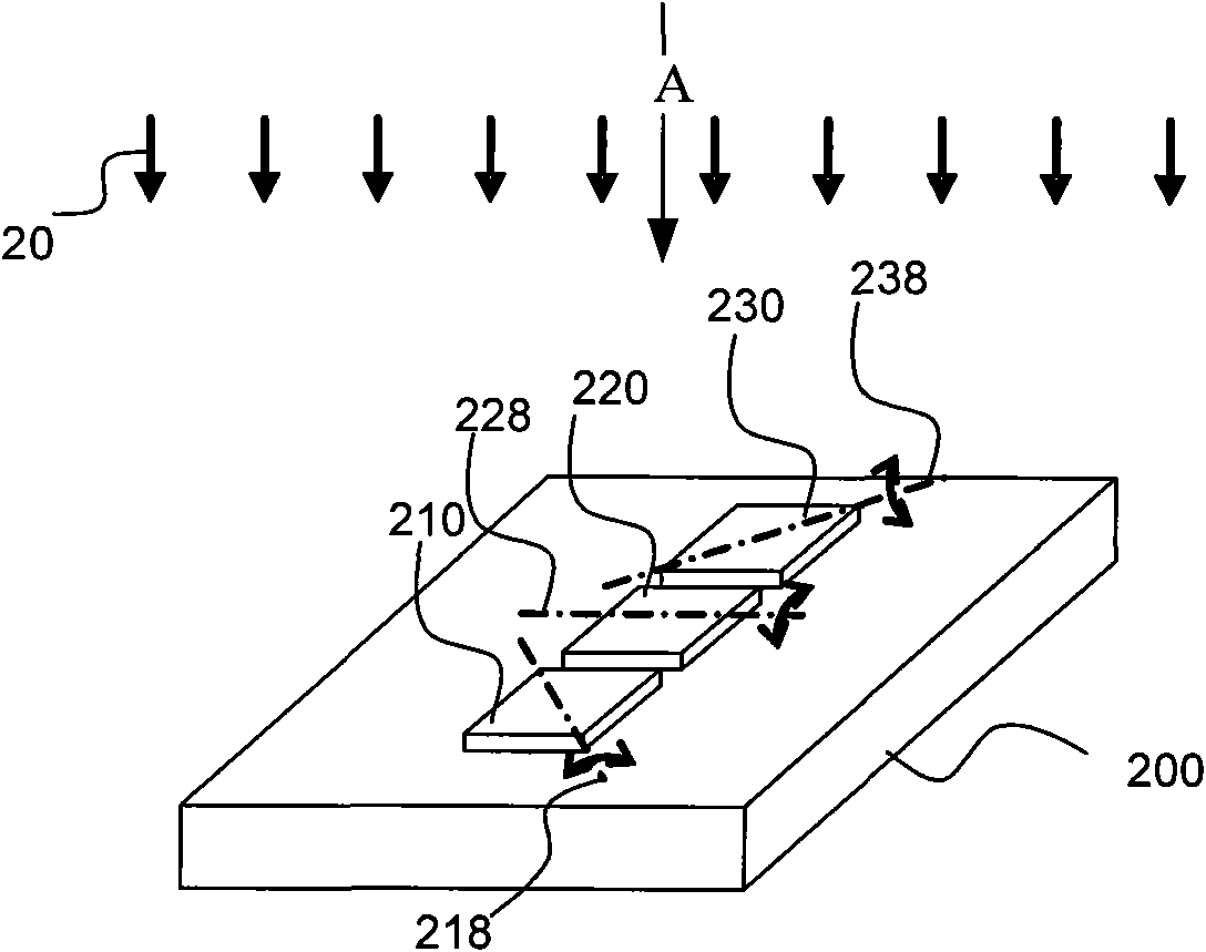
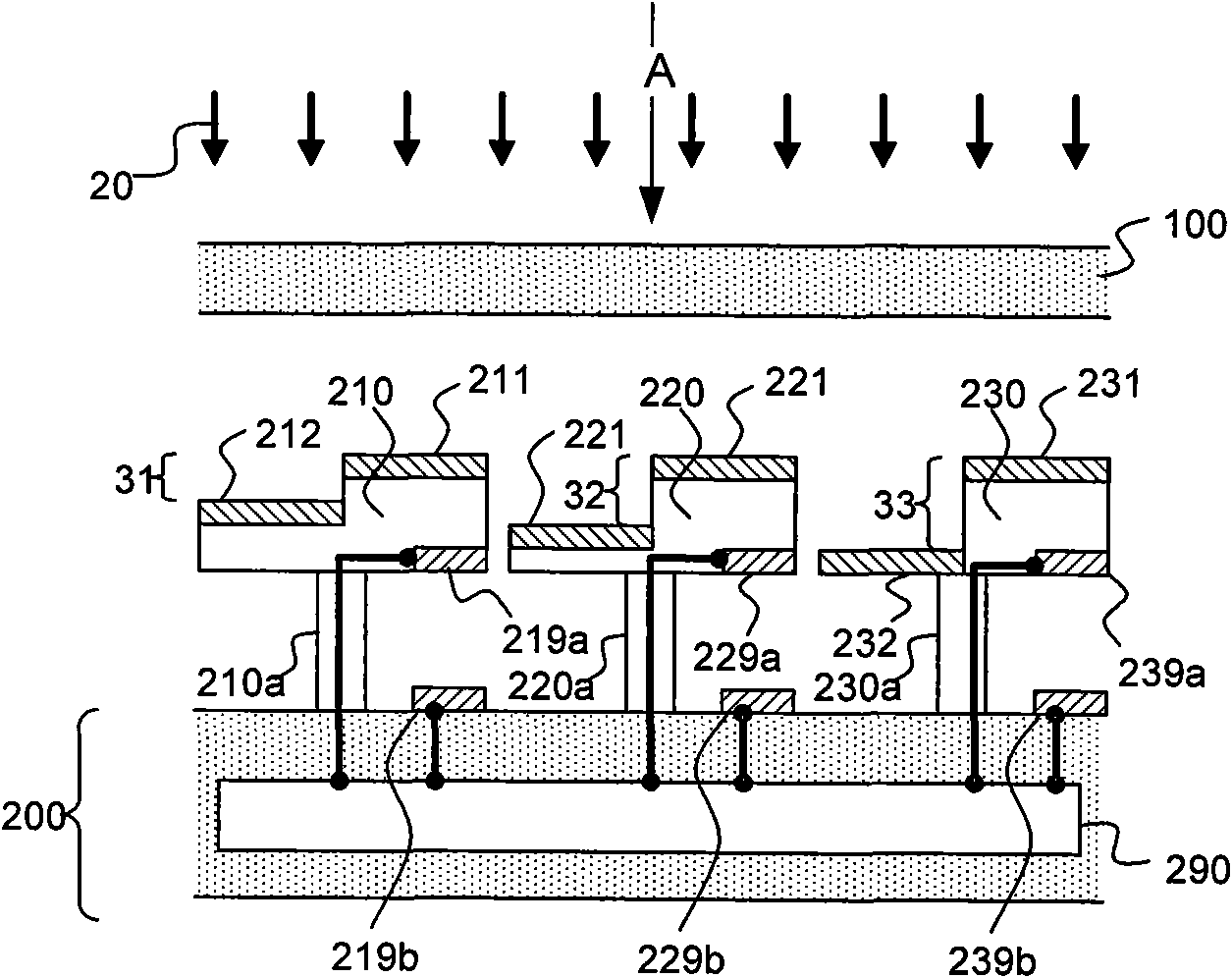
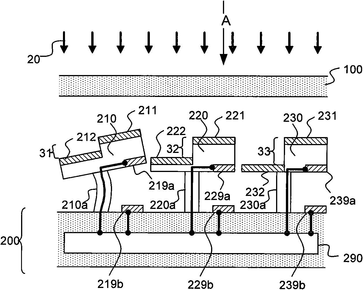
[0023] Such as figure 1 Shown is the schematic diagram of the three-dimensional structure of the micromirror display of the present invention, and the micromirror display includes a substrate 200, a first reflector 210, a second reflector 220 and a third reflector 230, and the first reflector 210 is arranged on and fixed on the substrate 200 On t...


PUM


Abstract

The invention provides a micro-mirror display which comprises a substrate, a first reflector, a second reflector and a third reflector, wherein the first reflector can rotate along a first axis and is used for reflecting first spectral band light in incident light by diffraction or interference between two conductive reflecting layers of the first reflector; the second reflector can rotate along a second axis and is used for reflecting second spectral band light in the incident light by diffraction or interference between the two conductive reflecting layers of the second reflector; the third reflector can rotate along a third axis and is used for reflecting third spectral band light in the incident light by diffraction or interference between the two conductive reflecting layers of the third reflector; the first reflector, the second reflector and the third reflector are separately arranged in a array mode, and the first axis, the second axis and the third axis are parallel with the substrate. The micro-mirror display provided by the invention can display with various colors, has simple optical path design, and does not need to carry out complex control for light beam with different colors.

Description

technical field [0001] Embodiments of the present invention relate to the field of display technology, and in particular to a micromirror display (MicroMirror Display). Background technique [0002] The Micromirror Device (Digital Mirror Device, MMD for short) used in projection equipment was originally proposed by Hornbeck in the US patent document US5600383. The DMD includes deflectable isomorphic mirrors (isomorphic mirrors) array. All mirrors are identical in that they reflect and modulate incoming light (eg, visible light). Accordingly, if different spectral bands of light need to be processed, for example, different colors need to be produced, a color image display is required. A color image display can be obtained through sequential processing by a single DMD. It is also possible to obtain a color image display through DMDs corresponding to each wavelength or color, that is, to combine three kinds of DMDs with a prism, and to process the light of each main color as...

Claims


Application Information

Patent Timeline
IPC IPC(8): G02B26/08
Inventor 河·H·黄
Owner XIAN YISHEN OPTOELECTRONICS TECH CO LTD
Learn More