Salient point forming device and method

A technology of bumps and convex surfaces, applied in the field of information disk drive devices, can solve the problems affecting the static performance of the load bar 111, the static performance of the magnetic head 104, and the read and write ability of the magnetic head 104, etc., achieving high precision, easy formation, Compensating for the effects of concentration constraints

Inactive Publication Date: 2010-12-29
SAE MAGNETICS (HK) LTD
View PDF3 Cites 0 Cited by
  • Summary
  • Abstract
  • Description
  • Claims
  • Application Information

AI Technical Summary

Problems solved by technology

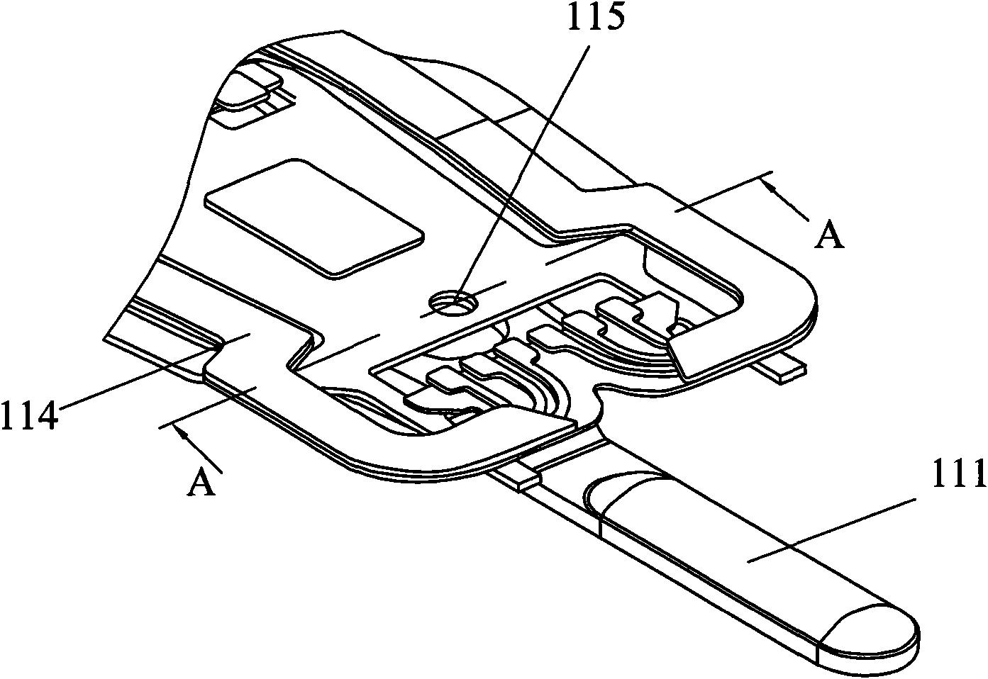
[0006] However, in the above-mentioned process of forming bumps 115 on the load bar 111 , because there is no preheating treatment for the load bar 111 , the load bar 111 rapidly and violently occurs during the stamping process of the forming pin 220 deformation, resulting in high stress at the junction of the load bar 111 and bump 115
This will af

Method used


Image

  • Salient point forming device and method
  • Salient point forming device and method
  • Salient point forming device and method

Examples


Embodiment Construction

[0039] The following will clearly and completely describe the technical solutions in the embodiments of the present invention with reference to the accompanying drawings in the embodiments of the present invention. Obviously, the described embodiments are only some, not all, embodiments of the present invention. Based on the embodiments of the present invention, all other embodiments obtained by persons of ordinary skill in the art without creative efforts fall within the protection scope of the present invention.

[0040] Figure 5 It is a schematic diagram of a bump forming device according to an embodiment of the present invention. refer to Figure 5 The bump forming device for forming bumps on predetermined positions of the load bars 411 includes a base 310 , forming pins 320 and a heating unit 330 . The base 310 includes a concave surface 314 and a through hole 312 adjacent to the concave surface 314 , the base 310 is disposed below the first surface 4112 of the load ba...


PUM


Abstract

The invention provides a salient point forming device for forming salient points on a preset position on a workpiece, which comprises a base with a concave surface, a heating unit and a molding pin with a spherical surface, wherein the base is arranged at the lower part of the workpiece; the heating unit is used for heating the preset position on the workpiece to improve the ductility of the preset position on the workpiece; the molding pin is arranged at the upper part of the workpiece and the spherical surface of the molding pin aligns with the preset position heated by the heating unit on the workpiece; and before the preset position on the workpiece is stamped by the molding pin, the heating unit effectively improves the ductility and malleability of the preset position on the workpiece, and the stress generated at junctions for salient points is smaller when the molding pin stamps the workpiece. The invention also discloses a salient point forming method, a head gimbal assembly and a manufacturing method thereof.

Description

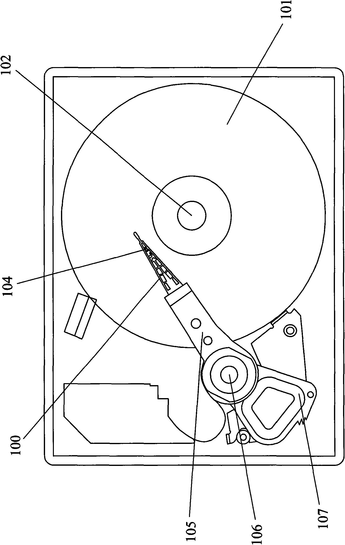
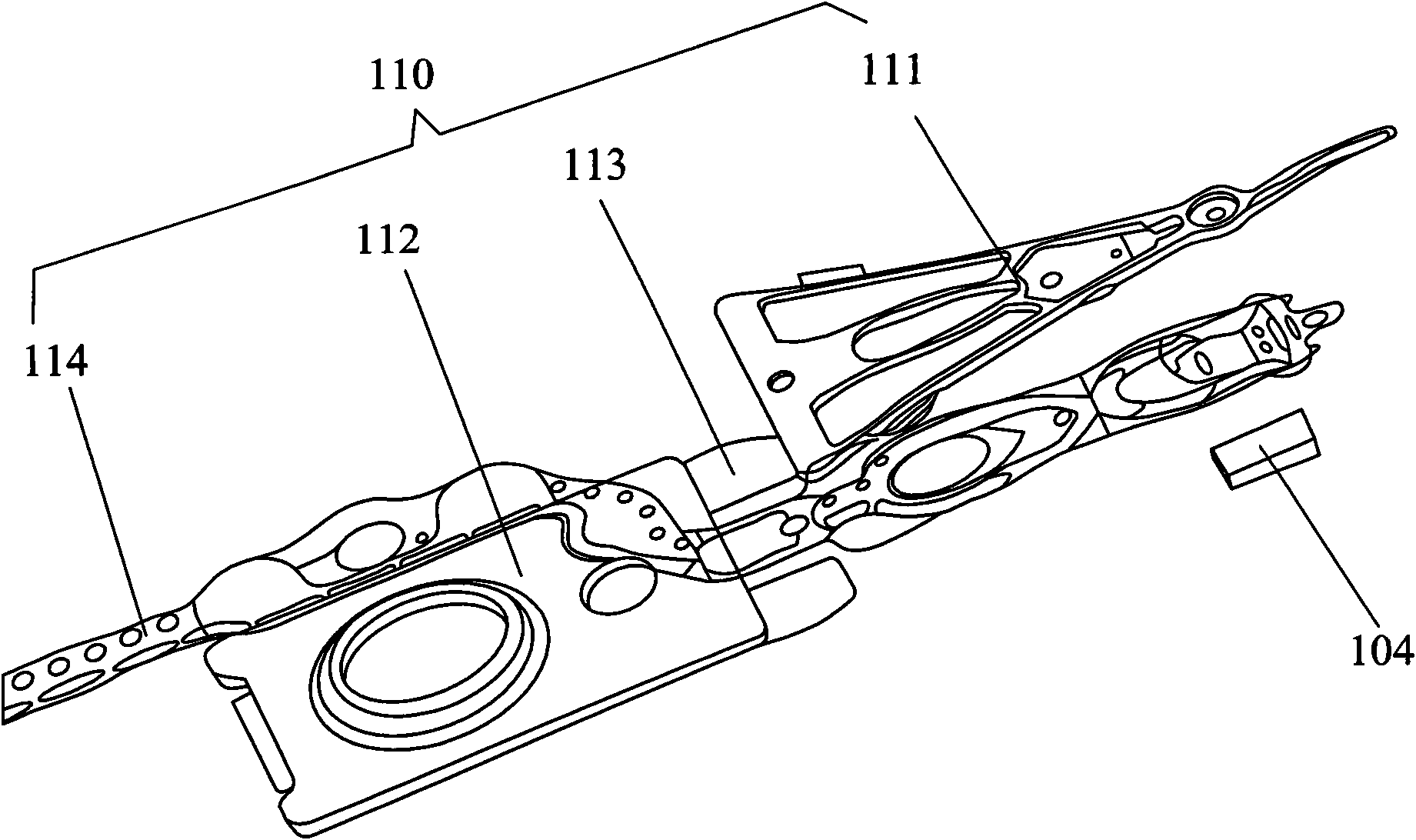
technical field [0001] The present invention relates to an information disk drive device, and more particularly to a device and method for forming bumps on a suspension member of a disk drive device. Background technique [0002] The well-known information storage device generally refers to a magnetic disk drive device, which stores information using a magnetic medium on which a movable magnetic head is placed for selectively reading or writing data from or to the magnetic disk. [0003] figure 1 A conventional disk drive unit is shown, and a disk 101 for high-speed storage of digital information mounted on a spindle motor 102 for rotating the disk 101 is shown. The HGA 100 includes a magnetic head 104 with a read / write head and a suspension 110 for mounting the magnetic head. The HGA 100 is connected to a driving arm 105 , and the driving arm 105 rotates around a bearing 106 . The voice coil motor 107 is used to control the rotation of the bearing 106 so as to control th...

Claims


Application Information

Patent Timeline
IPC IPC(8): G11B5/48
Inventor 陈灿华深谷浩何耀诚
Owner SAE MAGNETICS (HK) LTD
Why Eureka
Try Eureka