Power regulation device based on controlled silicon

A power regulation and power technology, applied in the direction of reactive power adjustment/elimination/compensation, harmonic reduction device, reactive power compensation, etc., can solve problems such as output voltage waveform distortion, improve power factor, reduce pollution, harmonic The effect of weight suppression

Inactive Publication Date: 2010-12-29
UNIV OF ELECTRONIC SCI & TECH OF CHINA
View PDF1 Cites 5 Cited by
  • Summary
  • Abstract
  • Description
  • Claims
  • Application Information

AI Technical Summary

Problems solved by technology

The output voltage waveform obtained by the traditional method is severely distorte

Method used


Image

  • Power regulation device based on controlled silicon
  • Power regulation device based on controlled silicon
  • Power regulation device based on controlled silicon

Examples


Embodiment 1

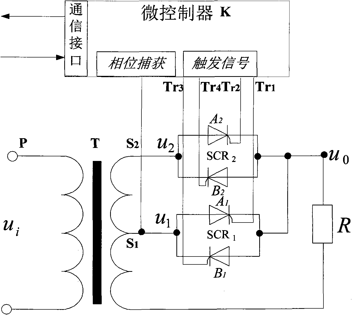
[0028] figure 1 It is a principle diagram of a specific embodiment of the thyristor-based power adjustment device of the present invention.

[0029] In this example, if figure 1 As shown, the power regulating device based on the silicon controlled rectifier of the present invention includes a transformer T, two sets of silicon controlled silicon SCR 1 、SCR 2 and microcontroller K.

[0030] Transformer T has two first-stage secondary outputs S with different transformation ratios 1 , Secondary secondary output S 2 . The primary P of the transformer T is connected to the main circuit of the power grid, and the voltage of the main circuit of the power grid is u i , the two secondary outputs S 1 , S 2 Output the first stage voltage u with the same phase and different voltage 1 and the second stage voltage u 2 , where the first stage voltage u 1 Less than the second stage voltage u 2 .

[0031] Two groups of SCRs 1 、SCR 2 The two secondary outputs of the transformer ...

Embodiment 2

[0081] The output voltage u of the power regulating device based on the silicon controlled rectifier in the present invention 0 The THDu is only involved in the superposition of the second stage voltage u 2 , the first stage voltage u 1 The ratio B=u 2 / u 1 It is related to the conduction angle α, and its relationship is:

[0082] THDu = 2 πθ - θ 2 2 π B - 1 + 2 π - θ , θ = 2 α - sin 2 α . - - - ( 11 )

[0083] Because the variation range of the conduction angle α is fix...

Embodiment 3

[0093] Figure 8 It is a principle diagram of another specific embodiment of the thyristor-based power regulating device of the present invention.

[0094] In this example, if Figure 8 As shown, the thyristor-based power regulator is the same as that shown in Embodiment 1, except that the microcontroller K adds a data sampling module, and the output voltage u on the load R 0 and current i 0 to obtain the power of the load R; the microcontroller K adjusts the conduction angle α according to the detected power of the load R: when the detected power of the load R is less than the power required by the load R, that is, in this embodiment, When the power of the load R set by the host computer is obtained, the conduction angle α is reduced, and when the detected power of the load R is greater than the power required by the load R, the conduction angle α is increased until the detected load R The power is equal to the power required by the load R, and the conduction angle α is ob...


PUM


Abstract

The invention discloses a power regulation device based on controlled silicon. According to the required power, a conduction angle alpha is regulated to be varied in the range of 0-pi, thus the output voltage can be continuously regulated in the range of a second-level voltage and a first-level voltage. The invention can realize continuous regulation of the load voltage value by using the power regulation device based on the controlled silicon and reduce the system oscillation. The fact that the invention can generate smaller harmonic distortion (THDu) compared with the phase-shift power regulation can be discovered by Matlab emulation. The small harmonic distortion (THDu) indicates that harmonic component is restrained and power factors are improved, thereby reducing pollution to power grid.

Description

technical field [0001] The invention belongs to the technical field of power adjustment of electrical equipment, and more specifically relates to a power adjustment device based on a thyristor. Background technique [0002] Thyristor, also known as thyristor, has the characteristics of high withstand voltage, large capacity, and small size. It is a high-power semiconductor device and is widely used in power electronic circuits. Thyristor can be subdivided into two kinds of one-way thyristor and two-way thyristor. Since only the one-way thyristor is used in the present invention, only the one-way thyristor will be introduced below, and for the sake of simplicity, it will be simply referred to as the thyristor in the following description, that is, if there is no special instruction, in the specification It is mentioned that the thyristor is a one-way thyristor. [0003] The thyristor has three pins of anode, cathode and control pole, and two working states of on and off. W...

Claims


Application Information

Patent Timeline
IPC IPC(8): H02J3/18H02J3/01
CPCY02E40/30Y02E40/40
Inventor 白利兵程玉华黄建国田书林
Owner UNIV OF ELECTRONIC SCI & TECH OF CHINA
Why Eureka
Try Eureka