Polarity testing device of horns

A technology of speaker polarity and testing device, applied in electrical components and other directions, can solve the problems of inability to accurately determine the phase difference of speakers, inability to guarantee the quality of earphone products, etc., and achieve the effect of improving the quality of the factory.

Active Publication Date: 2010-12-29
天键电声股份有限公司
View PDF4 Cites 14 Cited by
  • Summary
  • Abstract
  • Description
  • Claims
  • Application Information

AI Technical Summary

Problems solved by technology

[0003] At present, the speaker polarity testers on the market are all monophonic, so the speaker polarity tester has no ability to judge whether the left and right speakers are reversed. Therefore, mass-produced headphones, even if the left and right speakers are reversed , can not be tested with the existing speaker polarity tester, so the quality of the earphone produc

Method used


Image

  • Polarity testing device of horns
  • Polarity testing device of horns
  • Polarity testing device of horns

Examples


Embodiment Construction

[0029] A further detailed description will be made below in conjunction with the accompanying drawings and embodiments of the present invention:

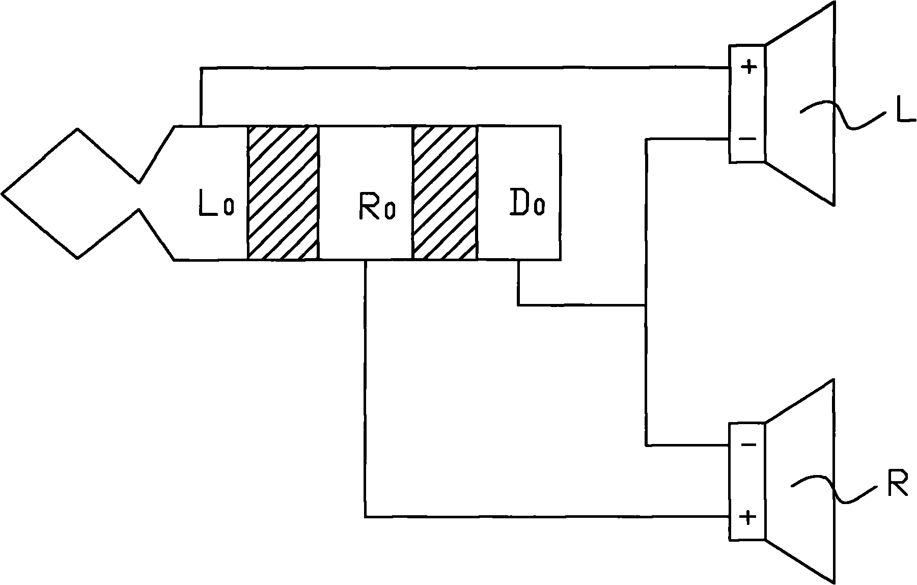
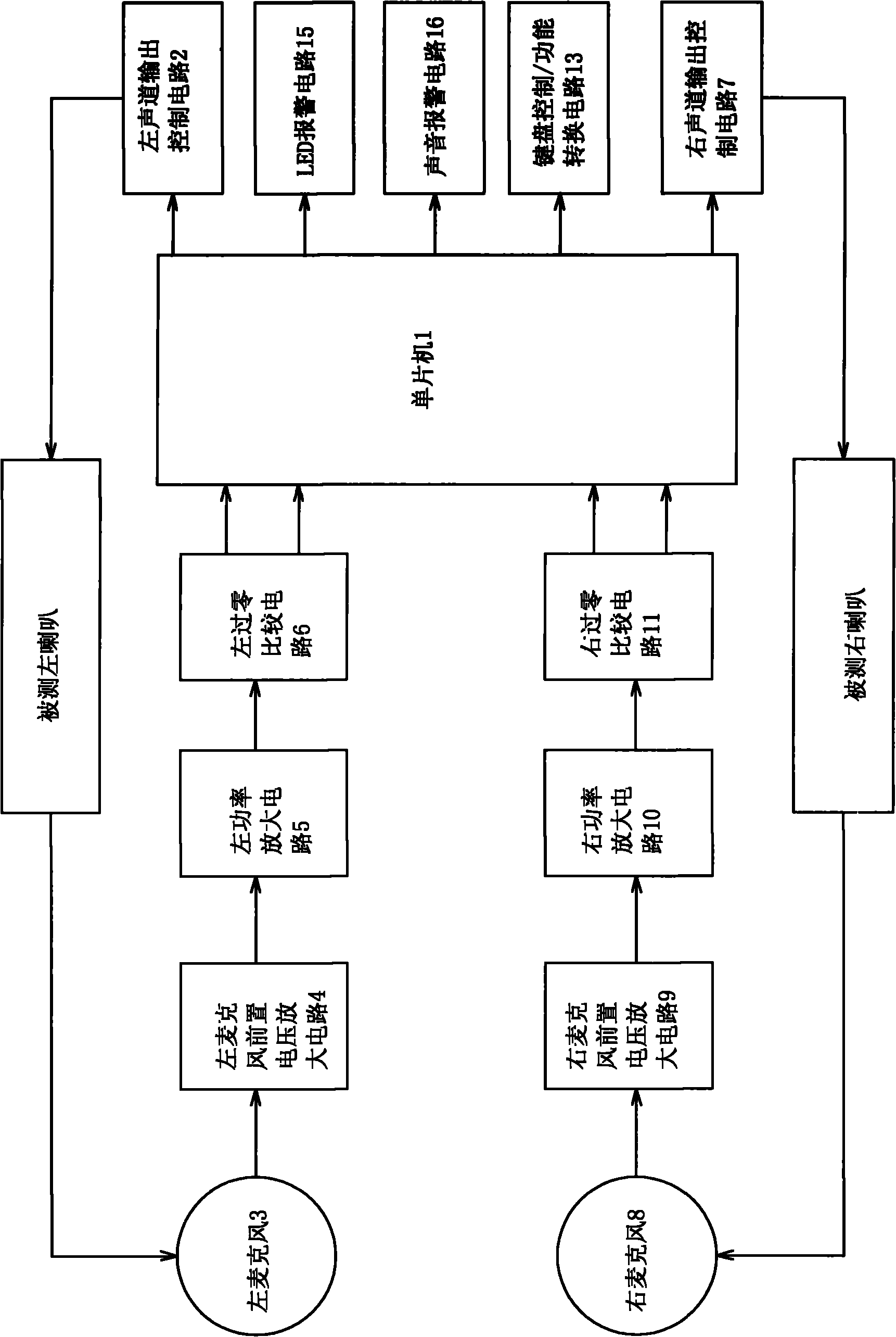
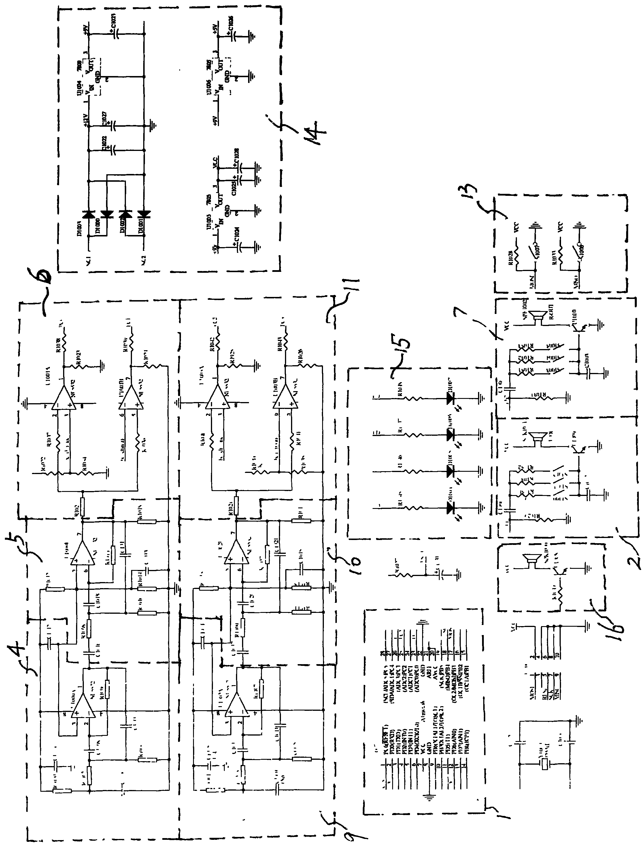
[0030] see Figure 2-5 , the present invention introduces a speaker polarity testing device, which includes: a single-chip microcomputer 1, a left channel output control circuit 2, a left microphone 3, a left microphone pre-voltage amplifying circuit 4, a left power amplifying circuit 5, and a left zero-crossing comparison Circuit 6, right channel output control circuit 7, right microphone 8, right microphone pre-voltage amplifying circuit 9, right power amplifying circuit 10, right zero-crossing comparison circuit 11, alarm circuit, keyboard control / function conversion circuit 13, power supply circuit 14.

[0031] The model of described single-chip microcomputer 1 is ATmega8, and it can produce the frequency of 1KZ (certainly also can be other frequency) Figure 4 In the first square wave signal, the square wave signal is used as...


PUM


Abstract

The invention discloses a polarity testing device of horns, and the device comprises a single chip microcomputer, a left sound channel output control circuit, a left microphone, a front voltage amplification circuit of the left microphone, a left power amplification circuit, a left zero-crossing comparison circuit, a right sound channel output control circuit, a right microphone, a front voltage amplification circuit of the right microphone, a right power amplification circuit, a right zero-crossing comparison circuit, an alarm circuit, a keyboard control/function conversion circuit and a power circuit. The device can conveniently detect whether earphones have the problem that a left horn and a right horn are in reversed connection and whether a single horn has the problem of reversed polarities, thereby helping improve the outgoing quality of the horns.

Description

[technical field] [0001] The invention relates to a horn polarity testing device. [Background technique] [0002] see figure 1 , is a schematic diagram of speaker wiring in the earphone, the positive pole of the left speaker L is connected to the signal input terminal L of the left speaker 0 Connection, the positive pole of the right horn R is connected to the signal input terminal R of the right horn 0 Connection, the negative poles of the left horn L and the right horn R are grounded. The so-called reverse connection of the left and right speakers means that the positive pole of the left speaker L is connected to the signal input terminal R of the right speaker. 0 Connect, the positive pole of the right speaker R and the signal input port of the left speaker L 0 Connect, and the negative poles of the left horn L and the right horn R are both grounded; the so-called reverse polarity of the horn means that the positive pole of the horn is grounded and the negative pole o...

Claims


Application Information

Patent Timeline
IPC IPC(8): H04R29/00
Inventor 刘洪军
Owner 天键电声股份有限公司
Why Eureka
Try Eureka